33
BH 5910 / 200217 / 190A
2-Hand control
(switch 1 in position 5)
4 pairs of 2-hand buttons Typ III A or 2 pairs of 2-hand buttons Typ III C
according to DIN EN 574 can be connected in this function. The number
of connected button pairs has to be selected on the device.
K1 and K2 can only be activated, if 3 conditions are fulfilled:
- First all button pairs have to be in initial position.
- Both buttons of 1 pair have to be pressed within 0.5 sec.
- All connected pairs have to be operated within 15 s.
If changeover contacts are used in the 2-hand buttons the switchover time
has to be less then 50 ms. If it is longer the outputs K1 and K2 are switched
off and the unit gives failure code 7. This failure is stored and can only be
reset by disconnecting the auxiliary supply.
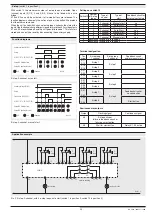
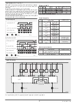
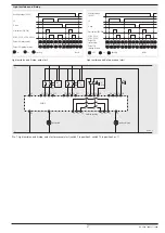
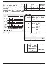
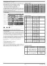
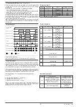
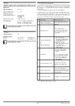
Two-hand control, 2 pairs of buttons with 2 NO contacts each
Function diagram
Button 2 S2 (S23/S24)
Auxiliary
voltage (A1/A2)
Button 1 S1 (S11/S12)
Button 1 S2 (S13/S14)
Button 2 S1 (S21/S22)
K1/K2 (13-14,
23-24, 33-34)
48 (no button activated)
58 (all buttons activated)
: off
: on
: flashing
M8444
<0,5s
0,5s
<15s
15s
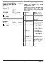
Set-up instructions
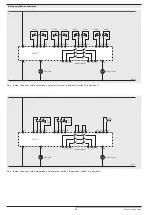
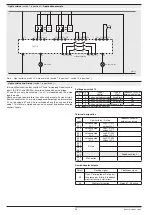
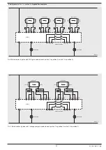
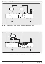
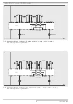
The device has to be connected as shown in the application examples. When
connecting the push-buttons in parallel or in series the safe function of the
relay is disabled. The buttons must be designed and installed in a way, that
it is not possible to manipulate or to operate them without intention.
The distance between push buttons and dangerous area must be chosen
in a way that it is not possible to reach the dangerous area after release of
one button before the dangerous movement comes to standstill.
The safety distance "S" is calculated with the following formula:
S = V x T + C
a) moving speed of person V = 1 600 mm/s
b) stopping time of the machine T (s)
c) Additional safety distance C = 250 mm
If the risc of accessing the dangerous area is prohibited while the push
buttons are pressed e.g. by covering the buttons, C can be 0. The minimum
distance has to be in this case 100 mm. See also EN 574.
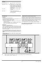
Semiconductor outputs
Output
Flashing signal
Continuous signal
48
Open gate, e-stop loop open
or failure in feedback circuit or
failure on simulation button
All buttons in initial
position. For a new start
all
buttons have to be
activated according to
the starting conditions.
58
Press acknowledge button.
All buttons are
activated,
K1, K2 are energized.
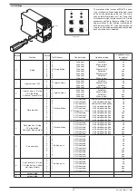
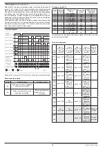
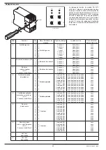
Settings on switch 10
Switch
10
Number of
button pairs
Type of button
contacts
Feedback circuit for
external contactors
0
1
2 NO contacts
no
1
2
2 NO contacts
no
2
3
2 NO contacts
no
3
4
2 NO contacts
no
4
1
2 C/O contacts
no
5
2
2 C/O contacts
no
6
1
2 NO contacts
yes
7
2
2 NO contacts
yes
8
3
2 NO contacts
yes
9
1
2 C/O contacts
yes
Terminal designation
Ter-
minal
Pair of buttons with
2 NO contacts each
Pair of buttons with
2 C/O contacts each
Feedback circuit for
external contactors
S11
S12
Pair 1, button S1
Pair 1, button S1,
NO contact
Pair 1, button S1,
common connector
S14
S13
Pair 1, button S2
Pair 1, button S1,
common connector
Pair 1, button S1,
contact NF
S21
S22
Pair 2, button S1
Pair 1, button S2,
NC contact
Pair 1, button S2,
common connector
S24
S23
Pair 2, button S2
Pair 1, button S2,
common connector
Pair 1, button S2,
NO contact
S31
S32
Pair 3, button S1
Pair 2, button S1,
NO contact
Pair 2, button S1,
common connector
S34
S33
Pair 3, button S2
Pair 2, button S1,
common connector
Pair 2, button S1,
NC contact
S41
S42
Pair 4, button S1
Pair 2, button S2,
NC contact
Pair 2, button S2,
common connector
Feedback circuit
S44
S43
Pair 4, button S2
Pair 2, button S2,
common connector
Pair 2, button S2,
NO contact
Acknowledge button

