background image

15

Engraving speed:Speed of MOOZ engraving
Deadhead speed : Movement speed of each axis
Border:  Width of the border

SizeX:Width of image

SizeY:Length of image

axisX:X coordinate of image

axisY:Y coordinate of image
Min power:Min laser power, the range is 0~100
Max power:Max laser power, the range is 0~100
Threshold:When the engraving type is Binary, you need 

to adjust the image exposure effect, drag the progress 

bar to adjust the exposure effect to the best, that is, the 

image and the background are black and white distinct.

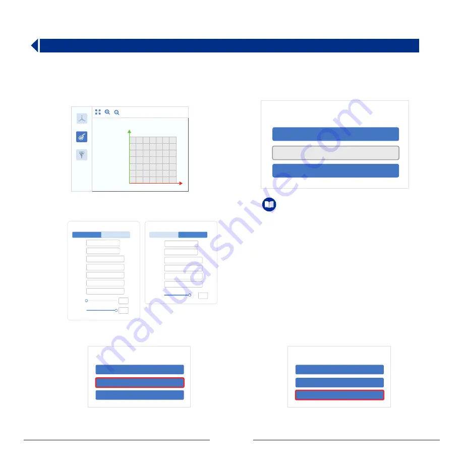
Laser parameter description:

Prerequisites :

Computer has downloaded and installed MOOZStudio.

The download path is https://www.dobot.cc/downloadcenter/dobot-mooz.html#most-download .

Step 1 : 

Double-click MOOZStudio to enter the software 

                   interface., select Laser.

Step 2 : 

Click Open File to import image.

Step 3 :

 Set the image parameters according to different laser 

type (Gray, Binary). Generally there are no special requirements. 

Select the default parameters.

3.3 Use Software to Generate Gcodes

10

10

20

30

40

50

60

70

20 30 40 50 60 70

工作区

激光雕刻

CNC雕刻

Open File

File

Generate G-code

EXport G-code

Step 4 :

 Click Generate G-code to generate a G-code file.

Open File

Generate G-code

EXport G-code

File

Step 5 :

 Click Export G-code to save the G-code file to a USB 

                   flash drive.

Open File

Generate G-code

EXport G-code

File

Laser Option

Gray

Binary

Engraving

Speed:

mm/min

mm/min

mm

mm

mm

mm

mm

Deadhead

Speed:

Border:

SizeX:

SizeY:

axisX:

axisY:

Min 

Power:

Max 

Power:

300

500

1

51.435

76.2

0.794

0.794

0

100

Laser Option

Gray

Threshold:

209

Engraving

Speed:

mm/min

300

mm/min

Deadhead

Speed:

500

mm

mm

mm

mm

SizeX:

SizeY:

axisX:

axisY:

51.435

76.2

0.794

0.794

Binary

Содержание MOOZ-2 PLUS

Страница 1: ...INDUSTRIAL GRADE TRANSFORMABLE METALLIC 3D PRINTER V1 0 2020 07 2 PLUS...

Страница 2: ......

Страница 3: ...4 4 Use Software to Generate Gcodes 5 1 WiFi Transfer 3 2 Set the Zero Point 3 3 Use Software to Generate Gcodes III Laser Engraving IV CNC Carving 13 2 6 Printing Control 2 7 Power Loss Resume 11 12...

Страница 4: ...face Settings Interface Calibrate Auto Level Manual Level Zero Setting Automatic levelling Manual levelling Entrance to zero point setting interface Return Return Page backward Page forward Display su...

Страница 5: ...ed button For installing lament and testing extrusion performance provided that the nozzle is preheated to about 200 C Filament retraction button For removing lament provided that the nozzle is prehea...

Страница 6: ...operations will not change any settings Control motion of X Y Z axis linear actuators the corresponding operations will not change any settings Step distance switching buttons Return 1 10 Working Proc...

Страница 7: ...ling Z2 20 Z1 20 Z3 20 Switch Points Please place the calibration card between the nozzle and heated bed Press the Z Z buttons to adjust the height and move the calibration card back and forth until y...

Страница 8: ...ed 5 If your printer prints in the mid air the zero point must be wrongly set After correct zeroing and homing the coordinate of Z should be about 190 6 Please be prudent with the button pressing it w...

Страница 9: ...s Double click to install the software Select the installation directory It is recommended to keep the default click Next Select the features you need It is recommended to keep the defaults click Inst...

Страница 10: ...75 mm 0 4 mm mm 200 mm 190 mm 1 GCode avor Marlin G28 Home M104 S0 M140 S0 Retract the lament G92 E1 G1 E 1 F300 G28 X0 Y0 Z0 M84 G1 Z15 0 F2000 Move the platform down Prime the extruder G92 E0 G92 E...

Страница 11: ...n list on the upper middle corner of the interface and select Layer view to view the details of the slice Profile the model Adjust the model left click on the model four options and will appear on the...

Страница 12: ...ny hovering part the option must be switched on Generally Everywhere indicates that support can be added on the model itself If you select Touching build plate it indicates that support can be added o...

Страница 13: ...3D print functional module 2 After printing finished please wait until heated bed cools down to ambient temperature then bend the flexible gasket slightly to remove the print 1 After printing started...

Страница 14: ...er o The machine will power o automatically after nishing the current printing engraving carving process the Auto power o button is activated on default 1 Speed Control Model 1 gcode Printing 100 Y 20...

Страница 15: ...nt detection sensor 3 The lament detection sensor module has adopted modular design If you do not need the function or if the sensor is not working you can unplug the temperature sensor cable white fr...

Страница 16: ...us the laser and set zero point Control the X axis and Y axis to make the laser spot irradiated on the workpiece Press the Calibration button Press the Entrance to zero point setting interface button...

Страница 17: ...axis and Y axis to move the laser spot to desired position generally intersection at the lower left corner of the workpiece Note 1 For the laser engraving function the zeros of X Y and Z axes shall a...

Страница 18: ...k MOOZStudio to enter the software interface select Laser Step 2 Click Open File to import image Step 3 Set the image parameters according to di erent laser type Gray Binary Generally there are no spe...

Страница 19: ...e holes Install the length adjustment screw into the clamp Put the MDF plate on the dust washer and align the holes Adjust the position of the xture according to the size of the workpiece and tighten...

Страница 20: ...s the workpiece provided that the block shall not interfere movement of the tool 3 CNC chuck is easy to get rusty for long time exposure to moisture Please regularly apply anti rust oil In case of not...

Страница 21: ...l requirements Select the default parameters 10 10 20 30 40 50 60 70 20 30 40 50 60 70 CNC CNC Options Speed Carving V Bit Flat End Mill Deadhead Speed Curving Depth Step Depth Safety Height SizeX Siz...

Страница 22: ...3mm layer 120mm min 2mm layer 200mm min 1mm layer 260mm min Carving Depth Including the settings for maximum depth and minimum depth of embossment Step Depth The carving depth of each layer If the tot...

Страница 23: ...rface on MOOZ 2 PLUS Step 4 Click Transfer Gcode to transferring G code le When the progress bar shows 100 the transmission is successful The name format of the transferred le will be automatically mo...

Страница 24: ...ult You can click Open on the touch screen to close the protective cover Pease ensure your security and DO NOT TOUCH the laser beam and carving bit during the process after closing the protective cove...

Страница 25: ...the cleaning easier Be careful of hot nozzle Q The print falls off from the heated bed melted filament flowing upwards and clogging around the nozzle Q Unable to read Gcode files in U disk or microSD...

Страница 26: ...is caused by faulty temperature sensor or filament runout detector Refer to Section 6 4 for maintenance A 1 Check if nozzle temperature displays normally 2 Check if red indicator light inside the func...

Страница 27: ...e temperature display 300 Step 1 Remove the print head housing after loosening the screws with an Allen wrench as shown below Step 2 Loosen the screws on the right fan and remove the fan Step 3 Loosen...

Страница 28: ...27...

Страница 29: ......

Страница 30: ...tion If this equipment does cause harmful interference to radio or television reception which can be determined by turning the equipment o and on the user is encouraged to try to correct the interfere...

Отзывы: