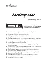


Electrical connection and sensors diagram
3
c
o
n
tr
o
l
fu
s
e
5
A
fu
s
e
5
A
L
N
P
E
L
N
L
N
P
E
L
N
R
o
o
m
t
h
e
rm
o
s
ta
t
D
H
W
s
e
n
s
o
r
R
e
e
d
r
e
la
y
P
E
P
E
M
Fun
1~
M
Feeder
1~
M
CH Pump
1~
Power supply
~230 V
T
h
e
rm
a
l
fu
s
e
C
H
b
o
il
e
r
s
e
n
s
o
r
F
e
e
d
e
r
s
e
n
s
o
r
L
N
P
E
M
DHW Pump
1~
Fig.3 Wiring diagram to connect power cables
Fig.4 Wiring diagram to connect sensors
Controller installation
4
1.
The controller is designed to be mounted on the boiler.
2.
Using the provided template for positioning of the controller.
3.
Install a screw in the boiler housing in the place indicated on the template.
4.
Decide on the method of routing the cable from the controller (rear, bottom) and
remove the corresponding caps from the housing.
5.
Slide the controller onto the fixed screw, use the other two screws to fasten it to
the boiler housing.
6.
Install the optional cables at the appropriate connectors and put them through
the holes in the housing.
7.
Protect the installed cables against pulling out, fixing then to the housing in
special sockets using the provided brackets and screws.
8.
Install the controller door.
4
Содержание Master 500
Страница 35: ......