4 |
P a g e
5.
Gain access to the rear of the screen & disconnect the 3 cables that are a
tt
ached.
6.
Set the unit aside for ease of installa
ti
on of the UCI.
7.
The free end of the 22 pin T-harness that is plugged into the radio head, is routed behind the dash to the screen
lo
cati
on.
8.
The 18 pin connector is inserted into the port labeled “Radio T-harness”.
9.
Locate the WHITE, ROUND connector that was removed from the screen. Insert this cable into the WHITE port
labeled “LVDS IN”.
10.
Take the provided LVDS cable and insert the BLACK end into the BLACK port (LVDS OUT). The other end will be
connected to the screen later.
11.
If installing a rear view camera, insert the 8 pin MOLEX plug into the port labeled “Video IN”. Of the connec
ti
ons
available, there’s;
a.
Twisted Pair – Used for factory installed camera only on the 4.3” screens. This input is not used on the
8.4” screens. On the 8.4” screens, the factory camera input is on the back of the radio head.
b.
Video 1, 2 & 3- Used for an
afte
rmarket camera input using composite video (yellow RCA connec
ti
on).
*Power connections for the rear view camera can be made at the cigarette lighter.
12.
If installing naviga
ti
on into the system, proceed to the naviga
ti
on install
ati
on sec
ti
on. Otherwise con
ti
nue to
step 13.
13.
A
ft
er all the connec
ti
ons are made, securely mount the UCI module in the dash.
14.
Connect the WHITE end of the provided LVDS cable into the screen. Make all other connec
ti
ons and reassemble
the radio/screen.
15.
Make the necessary changes in the SETUP menu & test.
16.
Using the p
lasti
c pry tool, gently pry around the dash panel to release the locking tabs. Take extra care when
releasing these tabs, they may fall from the dash panel and into the dash.
If Installing Directus Navigation
Once you complete step 12 of the UCI install
ati
on, con
ti
nue from this point.
1.
Plug in the supplied 24 pin Navig
ati
on harness into the port labeled NAVIGATION/AV.
2.
Route this cable down to the driver’s side under dash or any lo
cati
on that is secure. Be sure to securely fasten it
to ex
isti
ng wiring and brackets. Route away from any sharp or moving parts.
3.
Using Velcro, secure the module. For added stability, a large zip
ti
e should be used to secure the module in
place.
4.
Plug the routed cable from the UCI into the
Directus navig
ati
on unit.
a.
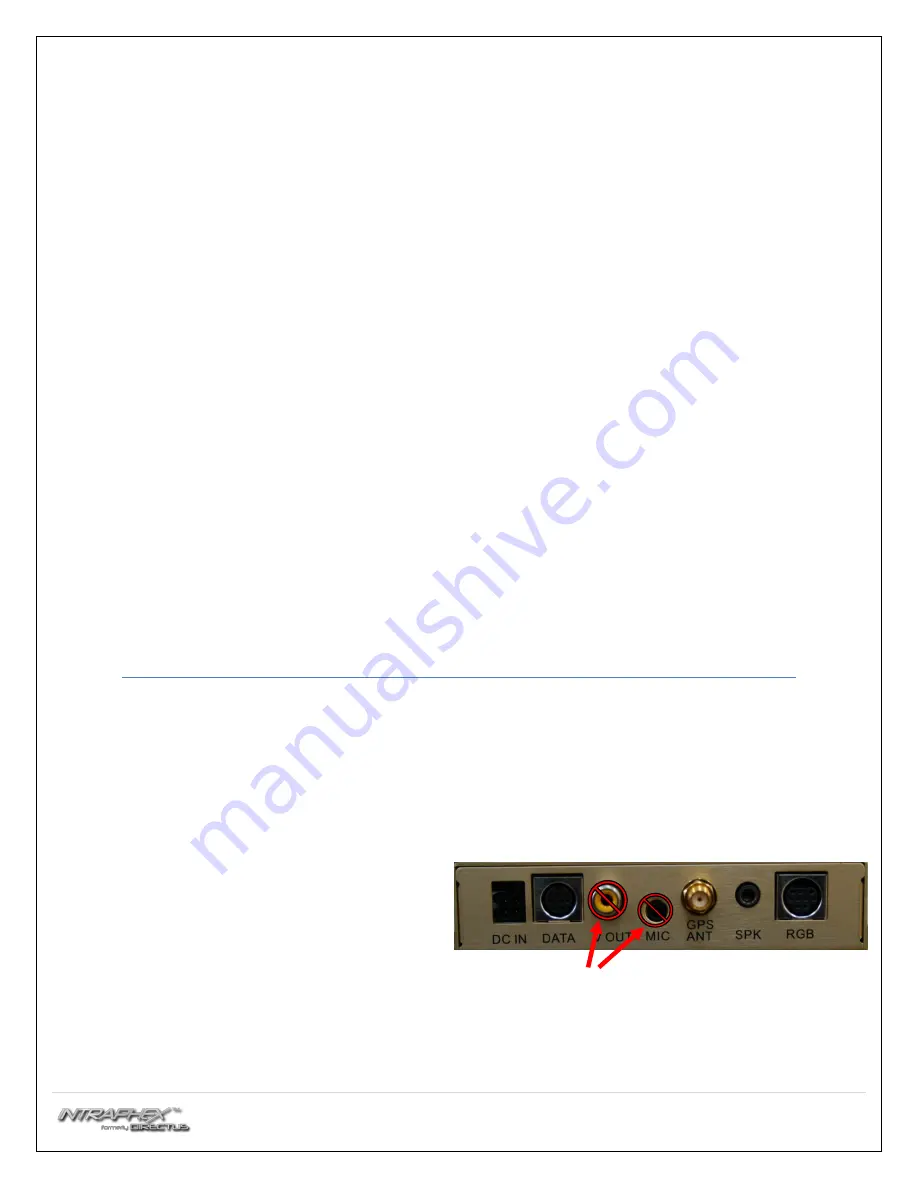
Black Din - RGB
b.
Grey Din – DATA
c.
4-pin MOLEX – DC IN
NOT USED
5.
Included in the kit is an external speaker, it is used for turn by turn navig
ati
on or any audio output from the
navig
ati
on unit. The speaker can be mounted on one of the metal rails running ve
rtical
ly under the steering
column. It is recommended that the speaker faces the opening under the steering column for best volume.
6.
Plug the speaker into the 3.5mm jack labeled SPK on the navig
ati
on.


