background image

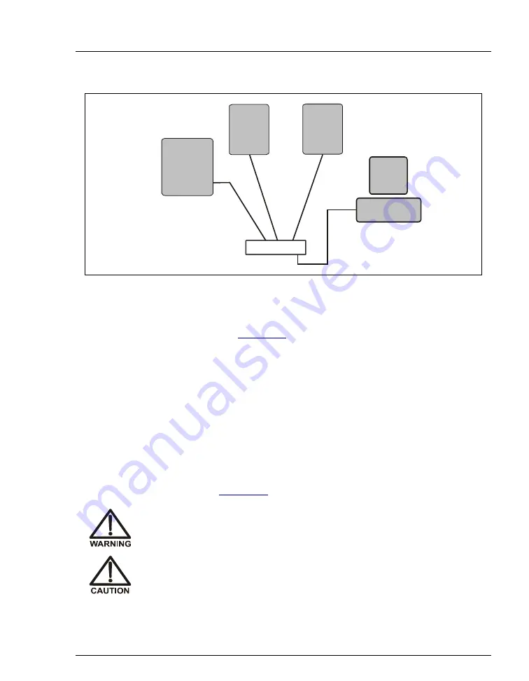
Figure 2-6.  Example Connections: Multiple Modules Connected to an External Hub

B

B

B

B

A

A

A

A

USB Cables

Plug the USB cable’s “B” connector 
into the USB receptacle on the ICS-90.
Plug the USB cable’s “A” connector 
into the “A” port on the USB hub.

Plug the USB cable’s “A” connector 
into the USB port on the PC.
Plug the USB cable’s “B” connector 
into the “B” port on the USB hub.

USB Hub

USB

Device

USB

Device

PC

ICS-90

2 • Installing the ICS-90 System

Doc. 031856-03  12/06

13

3. Plug the “A” connector of a USB cable into a USB port on the 

computer (see 

Figure 2-6

). 

4. Plug the “B” connector of the cable into a port on the USB hub.

2.3

Connecting the Power Cord

1. A label on the ICS-90 rear panel indicates the line frequency (60 Hz or 50 Hz) 

and voltage (110 to 120 VAC or 220 to 240 VAC) for which the system is 
designed. Make sure the frequency and voltage are appropriate for your 
location. If you are unsure, consult an electrician.

2. Connect the power cord (IEC 320 C13) from the main power receptacle on 

the rear panel (see 

Figure 2-4

) to a grounded power source.

SHOCK HAZARD—To avoid electrical shock, use a grounded 
receptacle. Do not operate the ICS-90 or connect it to AC power mains 
without an earthed ground connection.

The power supply cord is used as the main disconnect device. Make 
sure the socket-outlet is located near the ICS-90 and is easily 
accessible.

Содержание ICS-90

Страница 1: ...ICS 90 Ion Chromatography System Installation Instructions Document No 031856 Revision 03 December 2006...

Страница 2: ...HIS PUBLICATION IS PROVIDED AS IS WITHOUT WARRANTY OF ANY KIND DIONEX CORPORATION DOES NOT WARRANT GUARANTEE OR MAKE ANY EXPRESS OR IMPLIED REPRESENTATIONS REGARDING THE USE OR THE RESULTS OF THE USE...

Страница 3: ...ware 5 2 1 2 Installing the Software License 7 2 1 3 Starting the Chromeleon Server Monitor 10 2 2 Connecting the ICS 90 to the Computer 11 2 3 Connecting the Power Cord 13 2 4 Turning on the ICS 90 P...

Страница 4: ...e Pump 29 2 12 Setting the Pump Flow Rate ICS 90 only 30 2 12 1 Setting the Flow Rate 30 2 12 2 Recording the Measured Flow Rate 33 2 13 Setting the Pump Flow Rate ICS 90A only 34 2 14 Equilibrating t...

Страница 5: ...omeleon or Chromeleon Xpress before connecting the USB cable from the computer to the ICS 90 and before turning on the ICS 90 power 1 1 Facility Requirements Make sure the ICS 90 installation site mee...

Страница 6: ...t bottom Lifting from the front door will damage the door hinges Use caution when lifting the module it weighs 19 kg 42 lb Ne soulevez le ICS 90 que par le fond ou les c t s Son soul vement par la por...

Страница 7: ...pump in place during shipment 3 Use a Phillips screwdriver to remove the shipping screw 4 A screw holder is located to the right of the screw see Figure 1 1 Place the screw in the holder for safekeep...

Страница 8: ...ions 3 Follow the instructions in the computer installation guide to hook up the PC components 4 When you finish go to Section 2 1 to install the chromatography software North America Only NOTE These...

Страница 9: ...the Setup program then copies the software onto the hard disk 1 If this is a local computer log onto Windows XP or Windows 2000 as an administrator If this is a network computer log on as a user with...

Страница 10: ...rts when the computer is started and the program icon is displayed on the taskbar 7 After installing the software restart the computer 8 Microsoft Windows should automatically detect the ICS 90 and la...

Страница 11: ...stall the license you must first install a dongle on the computer and then enter a license Key Code in Chromeleon A dongle is an adapter that is connected to the parallel PC interface or USB port The...

Страница 12: ...e Key Code was entered before shipping If this is the case click Close and go Section 2 5 1 to create a timebase If Chromeleon or Chromeleon Xpress was not pre installed the Server Monitor status disp...

Страница 13: ...box see Figure 2 2 Click Dongle and then enter the Key Code provided with the Chromeleon license Click OK Figure 2 2 Server Configuration Properties 5 Check the Server Monitor status It should now dis...

Страница 14: ...r icon is not on the taskbar click Start on the taskbar and select All Programs or Programs depending on the operating system Chromeleon Server Monitor 2 If the server is not already running start it...

Страница 15: ...there are no unused USB ports on the PC connect the ICS 90 to an external USB hub P N 060392 and connect the PC to the hub If the dongle provided with Chromeleon or Chromeleon Xpress is for a USB port...

Страница 16: ...SB port on the PC USB cable s connector the ICS 90 PC To connect the ICS 90 to an external hub P N 060392 The ICS 90 Ship Kit P N 059947 includes one USB cable P N 960777 You must order another USB ca...

Страница 17: ...of the cable into a port on the USB hub 2 3 Connecting the Power Cord 1 A label on the ICS 90 rear panel indicates the line frequency 60 Hz or 50 Hz and voltage 110 to 120 VAC or 220 to 240 VAC for wh...

Страница 18: ...geschlossen werden Das Netzkabel ist das wichtigste Mittel zur Stromunterbrechung Stellen Sie sicher da sich die Steckdose nahe am Ger t befindet und leicht zug nglich ist ICS 90 Installation Instruct...

Страница 19: ...mebase 2 A clock icon appears under the server name with a default name highlighted To use the default name press Enter To use a different name type the name and press Enter Figure 2 7 shows an exampl...

Страница 20: ...igure 2 9 ICS 90 Configuration Properties Live Mode 5 On the General tab page Live Mode is selected by default Select the ICS 90 serial number from the drop down list If you are installing more than o...

Страница 21: ...on by a factor of 20 NOTE The Set Detection Limits option is not enabled unless Moduleware version 1 3 is installed in your ICS 90 8 Click OK to close the properties dialog box 9 Save the configuratio...

Страница 22: ...alled select View Default Panel Tabset or click on the toolbar to display the panel tabset NOTE If Chromeleon Xpress is installed starting the client automatically displays the panel tabset 3 To displ...

Страница 23: ...to the ICS 90 timebase 5 If the Control panel opens with the controls not yet active connect the ICS 90 to the Control panel by clicking the Connect button A dialog box appears see Figure 2 11 Figure...

Страница 24: ...the Disconnect and then the Connect button on the Control panel while observing the ICS 90 front panel LEDs If the ICS 90 and the chromatography software are communicating correctly the Power and Read...

Страница 25: ...bent pinched or elevated at any point A DCR waste backpressure tubing assembly P N 060214 is installed on the free end of the MMS III waste line see Figure 2 13 The assembly consists of a coupler and...

Страница 26: ...fitting and pipe thread reducer to connect the 3 mm 1 8 in ID tubing to a clean gas source The gas source should be regulated to between 0 55 and 0 83 MPa 80 and 120 psi 3 Push the other end of the tu...

Страница 27: ...dans de l eau d sionis e et non dans le r servoir vide Gie en Sie bei s urehaltigen Konzentraten beispielsweise dem Kationenelutionsmittel das Konzentrat immer in entionisiertes Wasser und nicht in de...

Страница 28: ...he neck of the eluent reservoir 6 Install the caps on the eluent and regenerant reservoirs and hand tighten 7 Place the reservoirs in the holders on the top cover of the ICS 90 8 Connect the liquid li...

Страница 29: ...shipped with the suppressor for details about suppressor operating pressure requirements 10 Connect the orange gas line from the eluent reservoir to the gas line on the air regulator outlet 2 9 Insta...

Страница 30: ...the union connecting COL IN and COL OUT and connect COL IN to the separator column inlet Connect COL OUT to the separator column outlet Check the arrow on the column label It should point toward the...

Страница 31: ...T and connect REGEN IN and REGEN OUT to the corresponding ports on the suppressor Figure 2 17 ICS 90 with Columns and Suppressor Installed Separator Column MMS III Suppressor Guard Column Side slot fo...

Страница 32: ...NOTE Do not pressurize the regenerant reservoir 1 Pull out the air regulator knob and turn it fully counterclockwise to ensure there is no pressure to the reservoir when the gas source is turned on 2...

Страница 33: ...Note The regenerant reservoir is unpressurized if the reservoirs are connected as described in Section 2 8 3 Verify that the waste lines are directed to a waste container 4 To start the liquid flow o...

Страница 34: ...isted for the column 2 Pull out the flow rate knob on the component mounting panel see Figure 2 18 and turn the knob slowly to the right to begin adjusting the pressure NOTES There is about a 10 secon...

Страница 35: ...ems in the ICS 90 Ship Kit luer fitting P N 024305 luer coupler P N 042806 1 mL syringe P N 016388 and 10 mL syringe P N 016387 You will also need a stopwatch or a clock or watch with a second hand th...

Страница 36: ...from the ELUENT IN line into a small graduated cylinder for 2 minutes c The collected eluent should be approximately equal to the desired flow rate in milliliters per minute For example for a flow rat...

Страница 37: ...e ICS 90 Control panel press the F8 key or select Control Command 2 Expand the Pump_ECD group and select MeasuredFlowRate see Figure 2 20 Figure 2 20 ICS 90 Chromeleon Commands MeasuredFlowRate 3 Ente...

Страница 38: ...stem Operator s Manual Document No 031851 The manual is included on the Dionex Reference Library CD ROM P N 055405 To set the pump flow rate Pull out the flow rate knob on the component mounting panel...

Страница 39: ...ing the AS40 Automated Sampler Optional 1 Open the front door of the ICS 90 and thread the outlet line from the AS40 through the side slot near the lower ICS 90 door hinge see Figure 2 17 2 Connect th...

Страница 40: ...llation Troubleshooting Problem When the ICS 90 power is turned on for the first time a Windows message box appears asking for a USB configuration file cmwdmusb inf Possible Cause The USB cable was co...

Отзывы: