8
TIG welding with “Lift”
In the TIG process welding is achieved by melting the two metal
pieces to be joined, with the possible addition of material from
the outside, using an arc ignited by a tungsten electrode. The
“Lift” type ignition used in
DIX PI 3506.M I / DIX PI 3006.M I
Puls / DIX PI 3506.M I Puls
equipments makes it possible to re-
duce tungsten inclusions on ignition to a minimum. The molten
bath and the electrode are protected by and inert gas (for ex-
ample, Argon). This type of welding is used to weld thin sheet
metal or when elevated quality is required.
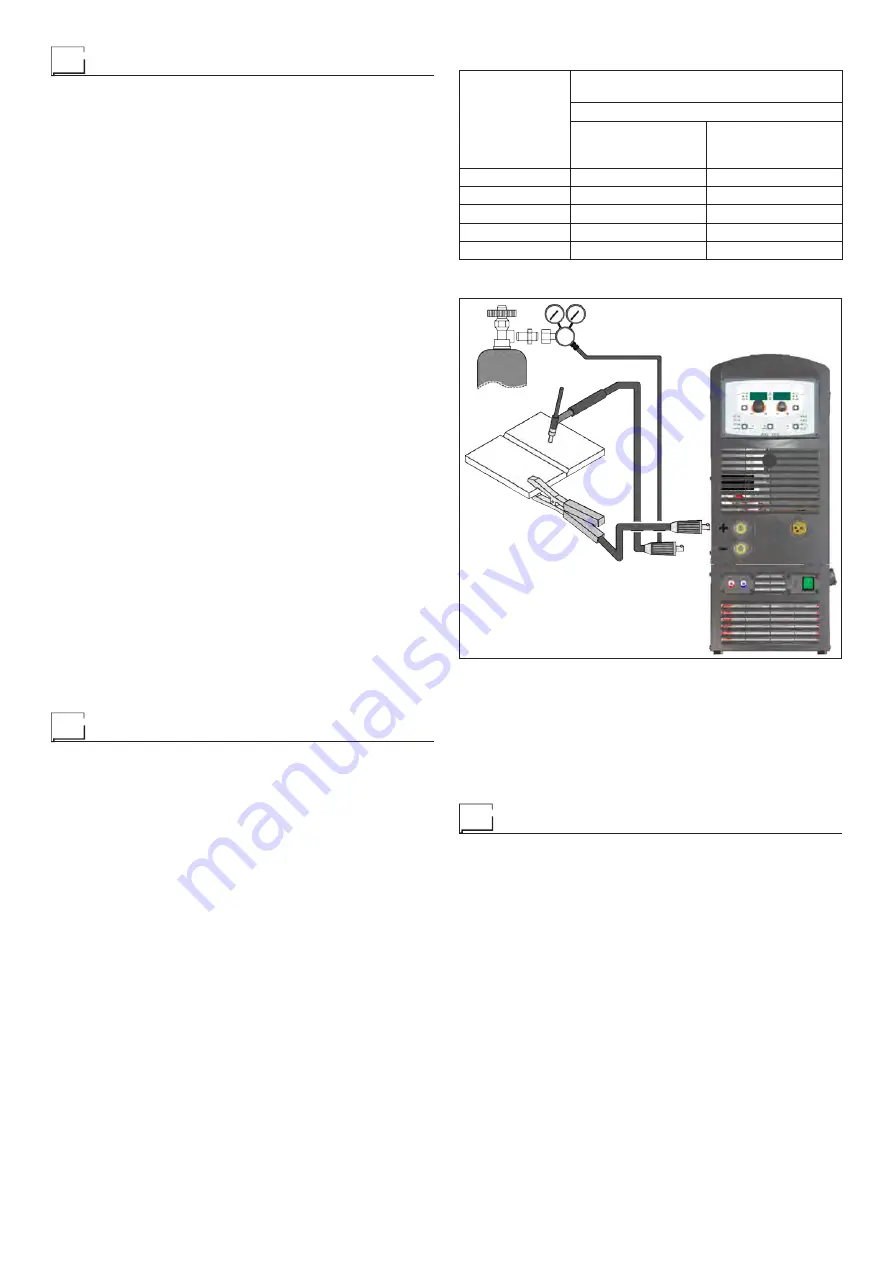
1) Connecting the welding cables (Fig. F):
•
Connect one end of the gas hose to the gas connecter on
the TIG torch and the other end to the pressure reducer
on the inert gas cylinder (Argon or similar).
•
With the welding power source switched off:
- Connect the ground cable to the snap-on connector
(positive).
- Connect the relative ground clamp to the workpiece or
to the workpiece support in an area free of rust, paint,
grease, etc..
- Connect the TIG torch power cable to the snap-on con-
nector marked - (negative).
2) Switch the welding welding power source on by moving the
power supply switch to I (Pos. 7, Fig. B).
3) Make the adjustments and do the parameter settings on
the control panel.
4) Open the gas cylinder and regulate the flow by adjusting
the valve on the TIG torch by hand.
5) Ignite the electric arc by contact, using a decisive, quick
movement without dragging the tungsten electrode on the
piece to be welded (“Lift” type ignition).
6) The welder has a SWS “Smart Welding Stop” system for
the end of TIG welding. Lifting up the torch without switch-
ing off the arc will introduce a slope down and it will switch
off automatically.
7) When you have finished welding remember to shut the
valve on the gas cylinder.
Table 5 shows the currents to use with the respective elec-
trodes for TIG DC welding. This input is not absolute but is for
your guidance only; read the electrode manufacturers’ instruc-
tions for a specific choice. The diameter of the electrode to use
is directly proportional to the current being used for welding.
Maintenance
ATTENTION:
Cut off the power supply to the equipment be
-
fore effecting any internal inspection.
DIX PI 3006.M I / DIX PI 3506.M I / DIX PI 3006.M I Puls /
DIX PI 3506.M I Puls
IMPORTANT:
For fully electronic welding welding power sourc
-
es, removing the dust by sucking it into the welding power
source by the fans, is of utmost importance.
In order to achieve correct functioning of the welding power
source, proceed as described:
•
Periodic removal of accumulations of dirt and dust inside the
equipment using compressed air. Do not point the jet of air
directly at the electrical parts as this could damage them.
•
Periodical inspection for worn cables or loose connections
that could cause overheating.
TORCH
The torch is subjected to high temperatures and is also stressed
by traction and torsion. We recommend not to twist the wire and
not to use the torch to pull the welder. As a result of the above
the torch will require frequent maintenance such as:
•
Cleaning welding splashes from the gas diffuser so that the
gas flows freely.
•
Substitution of the contact point when the hole is deformed.
•
Cleaning of the wire guide liner using trichloroethylene or
specific solvents.
•
Check of the insulation and connections of the power cable;
the connections must be in good electrical and mechanical
condition.
Table 5
Ø ELECTRODE
(mm)
ELECTRODE TYPE
Current adjustment field (A)
TIG DC
Tungsten
Ce 1%
Grey
Tungsten
Rare ground 2%
Turchoise
1
10-50
10-50
1,6
50-80
50-80
2,4
80-150
80-150
3,2
150-250
150-250
4
200-400
200-400
FIG. F
SPARE PARTS
Original spares have been specifically designed for our equip-
ment. The use of spares that are not original may cause vari-
ations in the performance and reduce the safety level of the
equipment. We are not liable for damage due to use of spare
parts that are not original.
Optional
AIR AND/OR WATER COOLED UP/DOWN TORCH
This command and works as an alternative:
•
To the ENCODER - SX knob on the welding welding power
source’s control panel. In “synergic” MIG MAG and “manual”
MIG MAG welding processes, by pressing the two right (+)
and left (-) buttons you can regulate the values for the syn-
ergic welding parameters.
•
To the ENCODER - DX knob on the welding welding pow-
er source’s control panel. In the JOB welding process, by
pressing the two right (+) and left (-) buttons you can scroll
the welding points set previously.
Содержание DIX PI 3006.M I Puls
Страница 12: ...12 2101AC34 DIX PI 3006 M I DIX PI 3506 M I...
Страница 13: ...13 2101AC33 DIX PI 3006 M I Puls DIX PI 3506 M I Puls...


