6
2 - Welding
1) Switch the welding welding power source on by moving the
power supply switch to I (Pos. 6, Fig. B).
2) Make the adjustments and do the parameter settings on
the control panel.
3) Load the wire using the torch button, after having removed
the wire guide nozzle from the torch to allow the wire to
come out freely, while loading (remember that the wire
guide nozzle must correspond to the diameter of the wire
used).
4) Open the tap on the cylinder slowly and adjust the reducer
knob to obtain a pressure of about 1,3 to 1,7 bar, and reg-
ulate the flow to a value between 14 and 20 lit/min to suit
the current used for welding.
5) The welding welding power source is ready to weld. Start
welding by moving close to the welding point and press the
torch button.
6) Once welding has been completed remove any slag, switch
off the welding power source (which is only to be done
when the fan is not running), and close the gas cylinder.
Spot welding
Welding can be done with or without gas. The substantial differ-
ence with MIG-MAG welding is essentially related to the torch
and the adjustments that must be made on the control panel.
•
Depending on the torch chosen and the work to be done, a
gas guide nozzle can be fitted on the torch that is specifical-
ly for spot welding (see Fig. E).
•
Use the control panel to select the spot-welding mode and,
if necessary, make the changes to the related “Special func-
tions - Fx”, which allows the welding power source to do this
specific type of welding.
To begin spot welding:
•
Place the gas guiding nozzle perpendicular on the workpiece
to be spot welded.
•
Press the torch button to start the welding current and wire
feed.
•
When the spot welding time expires (SPOT WELD TIME),
the wire feed stops automatically.
•
When the torch button is pushed again a new welding cy-
cle starts.
•
Release the torch button.
FIG. D
Interval welding (Stitch)
The substantial differences with the spot welding mainly con-
cern the adjustments that must be carried on the welding weld-
ing power source.
Use the control panel to select the interval welding mode and
then make the changes to the related “Special functions - Fx”,
which allows the welding power source to do this specific type
of welding.
To begin interval welding:
•
Press the torch button to start the welding current and wire
feed.
•
At this point the welding welding power source automatically
carries out a succession of welded portions (STITCH WELD
TIME) followed by a pause (STITCH WELD PAUSE), accord-
ing to the times entered previously. This procedure stops au-
tomatically when the TORCH BUTTON is released.
•
When the torch button is pushed again the torch begins a
new interval welding cycle.
MIG-MAG / Puls MIG / DOUBLE
Puls MIG Welding
To begin MIG-MAG / Puls MIG / DOUBLE Puls MIG welding,
carry out the following tasks (with the welding power source
switched off).
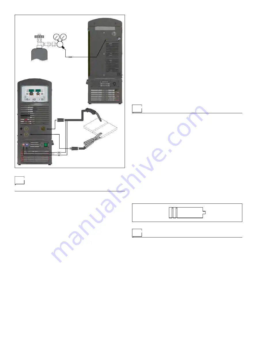
1 - Connecting the cables (Fig. C)
•
Connect the gas hose to the pressure reducer fitted on the
cylinder beforehand.
•
Screw the torch onto the centralised connection on the front
panel of the welding welding power source and connect the
feed (blue) and return (red) water hoses for cooling the torch
to the respective rapid couplings (coloured blue and red) on
the front panel of the cooling system.
•
Connect up the earthing system cable to the rapid coupling
marked by a - (negative) symbol and then the relevant ground
clamps to the piece being welded or to its support in an area
free from rust, paint and grease. Using particularly long earth-
ing cables reduces the voltage and causes some problems
from increased resistance and inductance of the cables that
could cause faulty welding. Follow instructions to avoid these
problems:
- Use earthing and extension cables with appropriate sec-
tion.
- Lay out the cables as a flat as possible to prevent them
from coiling up.
FIG. C
Содержание DIX PI 3006.M I Puls
Страница 12: ...12 2101AC34 DIX PI 3006 M I DIX PI 3506 M I...
Страница 13: ...13 2101AC33 DIX PI 3006 M I Puls DIX PI 3506 M I Puls...


