Product Information
Safety technics modular generation in metal housing version 08 dated: 2009-04-10 page 19 from 32
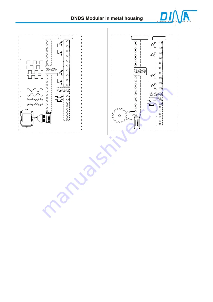
Motion detection via an encoder
Motion detection via 2 PNP proximity sensors
SPEED
UB
STOP
IN2
IN1
D1
D2
D3
D4
SH
R1
D5
D6
M11
M12
ENCODER
Measuring system
DNDS 1PMG
Inputs
outputs
Drives
shutdown,
Emergency
shutdown,
two canal
or series
connection
security
cover
lock
two canal
or series
connection
STOP SPEED
UB
OD
OS
A2
A1
0V
24V
44
43
34
33
24
23
14
13
SPEED
STOP
NC
NC
SPEED
STOP
Information
only
A
A*
B
B*
Sin
Sin*
Cos
or 1Vss
Cos*
1V-5V TTL
Inputs
DNDS 1PMG
SPEED
UB
STOP
IN2
IN1
D1
D2
D3
D4
SH
R1
F1
F2
F3
F4
outputs
Drives
shutdown,
Emergency
shutdown,
two canal
or series
connection
security
cover
lock
two canal
or series
connection
STOP SPEED
UB
OD
OS
A2
A1
0V
24V
44
43
34
33
24
23
14
13
SPEED
STOP
NC
NC
SPEED
STOP
Information
only
Requirements of the encoder
•
Encoder signal: Rectangular with amplitude of 0.5-5 V or sine/cosine signal with 1VSS.
•
Encoder frequency
≤
≤
≤
≤
300KHz
•
Encoder with high resistance outputs during malfunction.
•
2 tracks 90° out of phase, 2 signals per track that are 180° out of phase
•
The signals of encoder are not allowed to be generated synthetically
Fundamental
•
The monitoring of the Standstill on zero is not possible.
•
The monitored standstil frequency is 5Hz after the divisor with Encoder measurement messsystem. With resolver
measurement messsystem the change of the phase is monitored.
•
With Encoder select a large relationship mode2/ Standstill as possible: With axis 10 to 20, with spindles 20 to 50.
•
The divisor with mode 2 is if possible > 10.
•
With (mode 1/ mode 2)>(1250Hz/ mode 2-Freq) requires divisor variable
•
With divisor variable the divisor with mode 2 must be
≤
≤
≤
≤
2(31+1) or
≤
≤
≤
≤
4(31+1).
Monitoring not used
If less than 8 actuations should be monitored the not used monitoring modules must be removed from the unit and
replaced by a bridge circuit connector.
Bridge Circuit connectors
can be ordered from DINA.
Disable monitoring
If one monitoring system should be disabled, this could be done by connecting the input IN2 to 24V.
Faults and Errors
•
LED “SPEED” and “STOP” on the input and output modules do not light:
- The encoder is not connected.
- A proximity sensor failure.
•
LED “SPEED” and “STOP” on the monitoring module flash in 1 Hz intervals:
- Track A or B of encoder is missing.
- Proximity sensor at IN1 or IN2 is defective.
•
LED “SPEED” dos not light
- Registration of last crossing of the adjusted maximum speed.
To clear a fault the supply voltage must be switched off for at least 2s to reset the equipment (disconnect A1).
•
LED “STOP” and LED “SPEED” on the monitoring module flash in 2 Hz intervals:
- DNDS internal error.
- Error by improperly installed external signal lines.
The fault can possibly be eliminated by interruption of A1 for at least 2s.
Содержание DBDS 1VMG
Страница 1: ...DNDS Modular in metal housing Product information Safety for men and machines...
Страница 32: ......


