Product Information
Safety technics modular generation in metal housing version 08 dated: 2009-04-10 page 17 from 32
Output O2
switch off and the LED SPEED is not illuminated, if there is an overspeed, an external or an internal
failure, that causes a switch off of the outputs at the output modules.
O2 with overspeed and enabled speed output automatic restart:
O2 switch on again, if the actual speed is
≥
≥
≥
≥
10% less than the selected speed. The LED SPEED is illuminated.
O2 with overspeed and disabled speed output automatic restart:
O2 remain switched off and the LED SPEED remain dark also during standstill of the drive. O2 switch on and the
LED SPEED illuminates again, if the power supply will be turned off
≥
≥
≥
≥
2s
.
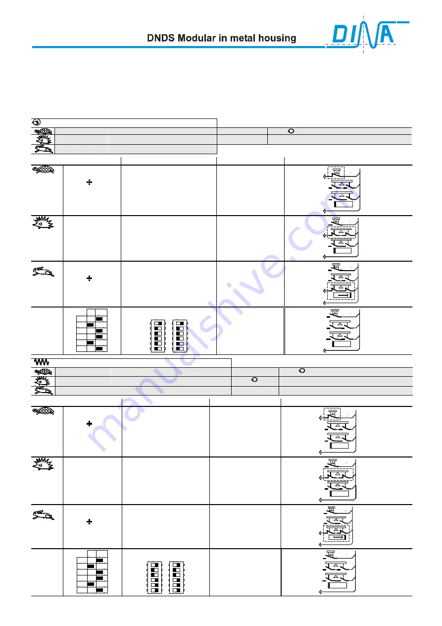
DNDS 1RG V1: monitoring spindle
800min
-1
Tool setting speed (mode2)
Encoder pulses
2 x 1I /
2000min
-1
Mode3
n
max
+ 10%
Switch off at
(+10% = Safety distance)
n
max
=18000min
-1
Automatic operating mode (mode1)
mode
calculation
note
External Contacts
Mode2
Step 1
Calculation of the
divisor ( ) and the
monitoring fre-
quency for mode2
Ratio mode 3 to mode 2 =
2000min
-1
/880min
-1
=2,5
2I x 880min
-1
/ 60s = 29,3Hz
29,3Hz
≈
≈
≈
≈
28,1Hz
Adjustment S3, S5
R1 and SH Table
positions 31 is possible =
28,1Hz
28,1Hz
=
mod 2-Frequency
Mode 2
SH
D2, D3, D4
24V
Tip switch
Permission key
Protection cover
Mode3
Step 2
Calculation of the
monitoring fre-
quency for mode3
2,5 x 28,1Hz =
70,25Hz
Adjustment S3, S5
R1 and SH table
positions 31 is possible =
70,25Hz
70,25Hz
=
mode 3-Frequency
Mode 3
R1
D2, D3, D4
24V
Tip switch
Permission key
Protection cover
Mode1
Step 3
Calculation of the
divisor ( ) and the
monitoring fre-
quency for mode1
19800min
-1
x 2I/ 60s =
660Hz
660Hz
= 100% of 660Hz
D & F-Table
D2, D3, D4 position 14
F1 to F4 position 15 =
660Hz
660Hz =
mode 1-Frequency
Mode 1
F1-F4
D2, D3,D4
24V
Tip switch
Permission key
Protection cover
DIP setting
Adjustment
S1
on
1
2
3
4
5
6
x 2
x 2
Table3: Position 32
1
2
3
4
5
6
o
n
S3
S5
1
2
3
4
5
6
o
n
Standstill
D2, D3,D4
24V
Tip switch
Permission key
Protection cover
DNDS 1RG V1: monitoring axis
v
= 2m x min
-1
Tool setting speed (mode2)
Resolver pulses 2 x 1I /
v
= 5m x min
-1
Mode3 (mode4)
5mm /
Ascending gradient
v
max
= 30m x min
-1
Automatic operating mode
v
+ 10%
Switch off at
(+ 10% = Safety distance)
mode
calculation
note
External Contacts
Mode2
Step 1
Calculation of the
divisor ( ) and the
monitoring fre-
quency for mode2
Ratio mode 3 to mode 2 =
5m x min
-1
/2m x min
-1
=2,5
2,2m x min
-1
/ 5mm = 440min
-1
440min
-1
x 2I /60s = 14,66Hz
14,66 Hz
≈
≈
≈
≈
14,5Hz
Adjustment S3, S5
R1 and SH Table
positions 24 is possible =
14,5Hz
14,5Hz
=
mode 2-Frequency
Mode 2
SH
D1, D2, D4
24V
Tip switch
Permission key
Protection cover
Mode3
Step 2
Calculation of the
monitoring fre-
quency for mode3
2,5 x 14,5Hz =
36,25Hz
Adjustment S3, S5
R1 and SH Table
positions 24 is possible =
36,25Hz
36,25Hz
=
mode 3-Frequency
Mode 3
R1
D1, D2, D4
24V
Tip switch
Permission key
Protection cover
Mode1
Step 3
Calculation of the
divisor ( ) and the
monitoring fre-
quency for mode1
33m x min
-1
/ 5mm = 6600min
-1
6600min
-1
x 2I / 60s = 220Hz
220Hz = 60% of 370Hz
D & F-Table
D1, D2, D4 position 7
F1, F2, F3 position 11 =
220Hz
220Hz
=
mode 1-Frequency
Mode 1
F1, F2, F3
D1, D2,D4
24V
Tip switch
Permission key
Protection cover
DIP setting
Adjustment
S1
on
1
2
3
4
5
6
x 2
x 2
Table3: Position 24
1
2
3
4
5
6
o
n
S3
S5
1
2
3
4
5
6
o
n
Standstill
D1, D2,D4
24V
Tip switch
Permission key
Protection cover
Содержание DBDS 1VMG
Страница 1: ...DNDS Modular in metal housing Product information Safety for men and machines...
Страница 32: ......


