Operator's Manual
DS7A - Constant Current Stimulator
Front Panel Controls
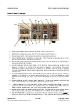
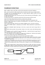
1. Mains Power ON/OFF switch (push ON, push OFF). When in the unit is on.
2. POWER ON is indicated by a green LED. When lit, indicates that the unit is on.
3. Manual trigger switch. Upon pressing this switch, a single output is produced.
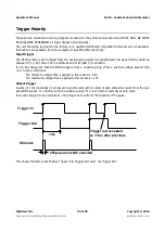
4. A valid TRIGGER signal is indicated by a amber LED. A flash indicates a valid trigger signal - either
from an external source or the manual push button.
5. Pulse Duration switch that sets the duration between 50 µs and 2 ms (2000 µs) in 6 steps (DS7A) or
50µs and 200µs (DS7AH, pictured).
6. Current Amplitude control of output pulses. For the DS7A this gives a continuously variable current
between 0 - 10 mA (or 0 - 100 mA if the x10 range is selected). For the DS7AH this gives a
continuously variable current between 0 - 100 mA (or 0 - 1000 mA if the x10 range is selected).
The current dial assembly includes a user engaged lock, which can be used to prevent the dial being
turned in error.
7. x1 and x10 RANGE selection switch. For the DS7A this gives either an output range of 0 - 10 mA, as
indicated in the window of the Current Amplitude Control or 0 - 100 mA by multiplying Current
Amplitude Control display by a factor of ten. For the DS7AH both ranges are increased by a factor
of 10.
8. Voltage Amplitude Control of output pulses (maximum). This sets the maximum voltage that can
occur on the electrodes and is continuously variable between 100 - 400 V.
9. * Output Enable Switch. In the ON position, the unit is able to generate output pulses. In the OFF
position the patient is isolated from the electronics of the unit. Switching to the OFF position also
resets the FAULT indicator latch. NB: This is not the primary power supply switch.
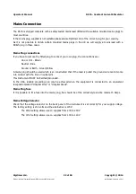
10. Isolated Output Sockets to patient stimulating electrodes. In normal polarity mode, the RED (upper)
socket will go positive with respect to the BLACK socket. The RED socket will be the ANODE.
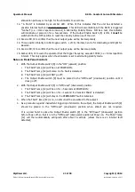
11. OUT OF COMPLIANCE is indicated by an amber LED. When lit, indicates that the unit was unable to
supply the current of the requested stimulus strength. This is usually because the resistance of the
Digitimer Ltd.
21 of 58
Copyright © 2014
File Ref: N:\Docs\Company\Manuals\DS7A\Issue-14\DS7A-iss14.odt
Last Revised: February 1, 2017


