21
COLOR VIDEO CAMERA
20
COLOR VIDEO CAMERA
23
COLOR VIDEO CAMERA
22
COLOR VIDEO CAMERA
MENU
9. Operating Camera
WDR MODE
WDR ELVEL
BACK LIGHT
BLC LEVEL
INITIAL
EXIT
ON, OFF
0 ~ 15
ON, OFF
0 ~ 15
ON, OFF
WDR
CAMERA ID
ZONE LABEL
NEGA/POSI
SHARPNESS
MIRROR
FREEZE
PROTOCOL
INITIAL
EXIT
GENERAL
000 ~ 255
SET
POSI/NEGA
0 ~ 15
NORMAL,MIRROR,VERTICAL,ROTATE
ON, OFF
DEF, P/D
ON, OFF
WB MODE
RED CONT
BLUE CONT
PUSH AUTO
INITIAL
EXIT
AWB
AUTO, HOLD, USER
NOT USE(AUTO, HOLD), 1~255(USER)
NOT USE(AUTO, HOLD), 1~255(USER)
NOT USE(AUTO, USER), OFF/PUSE(HOLD)
ON, OFF
A E
BRIGHTNESS
FLICKERLESS
SHUTTER SPD
AGC MAX SET
MAX FLD SET
INITIAL
EXIT
D/N MODE
LEVEL
FILTER DLY
INITIAL
EXIT
0 ~ 60
ON(PAL:x120, NTSC: x100), OFF
x250, x500, x1000, x2000, x4000, x10000
AGC OFF, LOW, MID, HIGH
OFF, 2~20 FLD, 40 FLD, 80 FLD, 160 FLD
ON, OFF
AUTO, DAY, NIGHT, EXT
0 ~ 200
0 ~ 15 SEC
ON, OFF
D & N
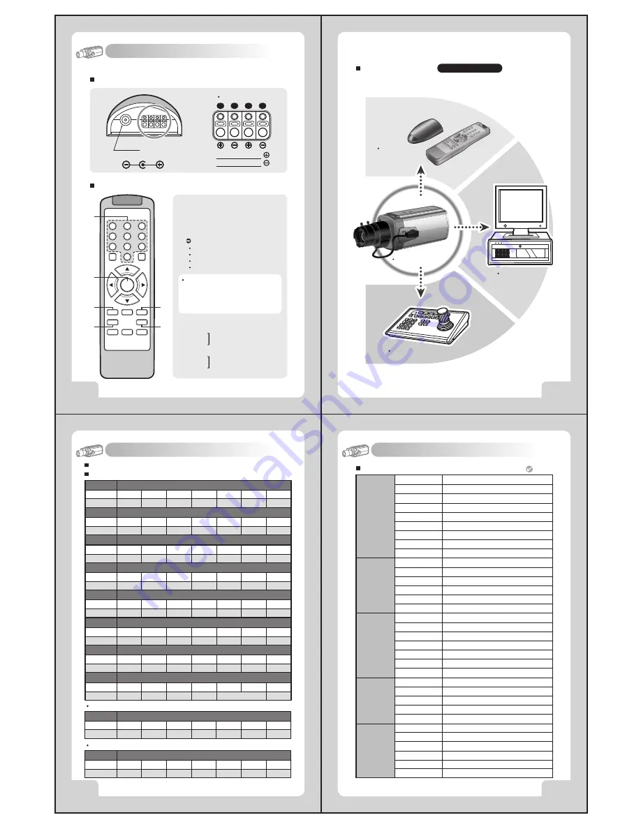
Configuration of The Menu
Receiver
Remote Control
7. Remote Controller Operation
(Pelco-D)
1
2
3
4
Power
DC 12V, 500mA
RS-485 Signal
- White Terminal :
- Black Terminal :
①
Camera Selection
- After camera connects with receiver,
firstly check camera I.D.
②
Menu (PROG): Shows / Hides Menu.
Moves up and down items.
③
(TELE):
④
(WIDE):
- Press camera I.D. number(1~39 buttons)
on the top of wireless remote controller.
Caution :
Usually camera I.D. number
are selected from No.1 to No.39.
over I.D. No.40, you will have a use limit.
- Initial camera I.D. number is set up No.0
when it takes out of manufacturer's warehouse.
Example: ZOOM IN
I.D. No.5: Press 5 +<TELE>
I.D. No.15: Press <F1>+ 5 +<TELE>
I.D. No.24: Press <F2>+ 4 +<TELE>
I.D. No.34: Press <F3>+ 4 +<TELE>
Set data for the selected items.
⑤
(NEAR):
⑥
(FAR):
④
⑤
③
⑥
②
①
F1
NEAR
FAR
FOCUS
F3
WIDE
F2
TELE
ZOOM
AUTO
SEQ
PAN
PROG
A
7
4
1
6
9
A
0
8
5
3
2
The remote controller is optional item.
Cable Connection
Pelco-D/ RS-485
Receiver &
Remote Control
Pelco-D Keyboard
DVR System
Signal (RS-485)
8. Communication Protocol
Power On
Function
MSG
BYTE 1
0xFF
BYTE 2
CamID
BYTE 3
0x88
BYTE 4
0x00
BYTE 5
0x00
BYTE 6
0x00
BYTE 7
Checksum
Power Off
Function
MSG
BYTE 1
0xFF
BYTE 2
CamID
BYTE 3
0x08
BYTE 4
0x00
BYTE 5
0x00
BYTE 6
0x00
BYTE 7
Checksum
Pelco D Stop
Function
MSG
BYTE 1
0xFF
BYTE 2
CamID
BYTE 3
0x00
BYTE 4
0x00
BYTE 5
BYTE 6
BYTE 7
Checksum
Menu On / Off
Function
MSG
BYTE 1
0xFF
BYTE 2
CamID
BYTE 3
0x40
BYTE 4
0x00
BYTE 5
0x00
BYTE 6
0x00
BYTE 7
Checksum
Focus Far
Function
MSG
BYTE 1
0xFF
BYTE 2
CamID
BYTE 3
0x00
BYTE 4
0x80
BYTE 5
0x00
BYTE 6
0x00
BYTE 7
Checksum
Focus Near
Function
MSG
BYTE 1
0xFF
BYTE 2
CamID
BYTE 3
0x01
BYTE 4
0x00
BYTE 5
0x00
BYTE 6
0x00
BYTE 7
Checksum
Zoom Wide
Function
MSG
BYTE 1
0xFF
BYTE 2
CamID
BYTE 3
0x00
BYTE 4
0x40
BYTE 5
0x00
BYTE 6
0x00
BYTE 7
Checksum
Zoom Tele
Function
MSG
BYTE 1
0xFF
BYTE 2
CamID
BYTE 3
0x00
BYTE 4
0x20
BYTE 5
0x00
BYTE 6
0x00
BYTE 7
Checksum
PELCO "D" Byte Format
Command Message
-RS-485,2400bps,1 Start bit,8 data bits,1 stop bit,no parity
Menu On / Off
Function
MSG
BYTE 1
0xFF
BYTE 2
CamID
BYTE 3
0x00
BYTE 4
0x23
BYTE 5
0x00
BYTE 6
0x5F
BYTE 7
Checksum
Menu On / Off
Function
MSG
BYTE 1
0xFF
BYTE 2
CamID
BYTE 3
0x00
BYTE 4
0x03
BYTE 5
0x00
BYTE 6
0x62
BYTE 7
Checksum
Pelco Keyboard (95+ PATTERN)
V/D Keyboard (Set 98)
Don't care


