


11
COLOR VIDEO CAMERA
10
COLOR VIDEO CAMERA
9
COLOR VIDEO CAMERA
8
COLOR VIDEO CAMERA
5
.
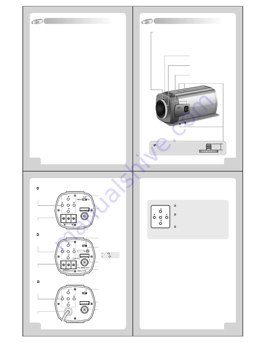
Name and Function
1. Wide Dynamic Range (WDR)
4. Fine Picture Condition Under Very Low Illumination (Sense up)
1/3 high density CCD and digital processor permit high quality pictures
to be captured in very low light condition.
SS-II DSP chip built-in SONY allows the camera to find the best picture
conditions in any environment and automatically gives a necessary
light level compensation, so you can always obtain the clear picture,
the finest detail and perfect light contrast.
5. VIDEO/ MANUAL/ DC Lens Selectable
The camera accepts 3 types of lenses (VIDEO/ MANUAL/ DC) and is
set with the VIDEO/ ELC/ DC selection switch.
6. Electronic Iris
The electronic iris shutter is automatically controlled at the speed of
1/60~1/10,000sec (NTSC Models), 1/50~1/10,000sec (PAL Models)
7. Controlled by OSD menu and RS-485
8. Privacy Zone
You can control the camera using OSD menu and RS-485 jack at a remote place.
3. High Resolution
The horizontal resolution of 480TV lines at Color mode can be achieved
by using a high density CCD having Double Speed 410,000 pixels
SONY CCD, which provides clean, noiseless and reliable pictures.
2. Day & Night
The camera provides automatic mode changeover by sensing day or
night conditions. It can change color mode in the day condition for
optimal color and BW mode in night condition for clear identification.
4
.
Features
CS-Mount Holding Screw
Used to readjust back focus of the camera. There are two back
focus lock screws. These must be loosened before the camera
may be back focused.
Loosen the lock screws using the L-wrench to turn the CS-mount
lens adaptor, and tighten the lock screws after adjustment.
Tripod Mounting Hole
Used to install the camera on an optional tripod. The tripod
must be equipped with the screw specified as shown below.
Auto Iris Lens Connector
Used to connect Auto Iris Lens plug.
C-Mount Lens Adapter
Used to attach C-mount lens.
CS-Mount Lens Adapter
Used to attach CS-mount lens.
1/4"- 20 UNC (20 THREAD)
L : 4.5mm±0.2mm (ISO standard),
or 0.197" (ASA standard)
L
①
Function Selection Switch
Functions can be setup using 5 buttons on the camera's rear panel.
②
Lens Selection Switch
Used to choose DC or VIDEO or ELC according to the type of your Lens.
③
V.PHASE Adjustment V.R (AC 24V / DC 12V Input Model)
If the camera is to be used in LineLock mode, the vertical phase may
require adjustment to synchronize the vertical phase of the camera with
other camera in the system. Make this adjustment when the vertical
phase of the camera does not match with other cameras or systems.
For correct adjustment, use a multi-channel oscilloscope.
The V.PHASE adjustment can be readjusted.
④
Remote Jack (See page 19)
Used to connect remote plug.
⑤
POWER Input Terminal
Used to connect an AC 24V or DC 12V power source.
Used to connect a DC 12V power source.
Used to connect an AC 100V~AC 240V power source.
⑥
VIDEO OUT Jack:
Used to connect an external video monitor in jack.
DC
VIDEO
ELC
VIDEO OUT
POWER INLET
AC 24V/DC 12V Input Model
③
V.PHASE
Adjustment V.R
①
Function
Selection
⑥
Video Out Jack
④
Remote Jack
②
Lens Selection
Swicth
⑤
Power Input
Terminal
Left( ):Internal
Right( ):External
DC 12V Input Model
①
Function
Selection
⑥
Video Out Jack
④
Remote Jack
②
Lens Selection
Swicth
⑤
Power Input
Terminal
AC 100V~AC 240V Input Model
①
Function
Selection
⑤
Power AC IN
⑥
Video Out Jack
④
Remote Jack
②
Lens Selection
Swicth
MENU
( )
( )
T( )
W( )
MENU
( )
( )
T( )
W( )
CONTROL
VIDEO OUT
Class 2 Only
MENU
( )
( )
T( )
W( )
CONTROL
DC 12V
DC
VIDEO
ELC
V.PHASE
MENU Buttons : Used to access menu mode.
Also used to essape menu mode.
UP/DOWN Buttons : Used to choose the desired
menu item. It also moves the cursor up or down
in the menu screen.
LEFT/RIGHT Buttons: Used to change the parameter
of the selected menu item. It also moves the cursor
the left of right in the menu screen.
MENU
( )
( )
T( )
W( )


