www.dfi.com
1
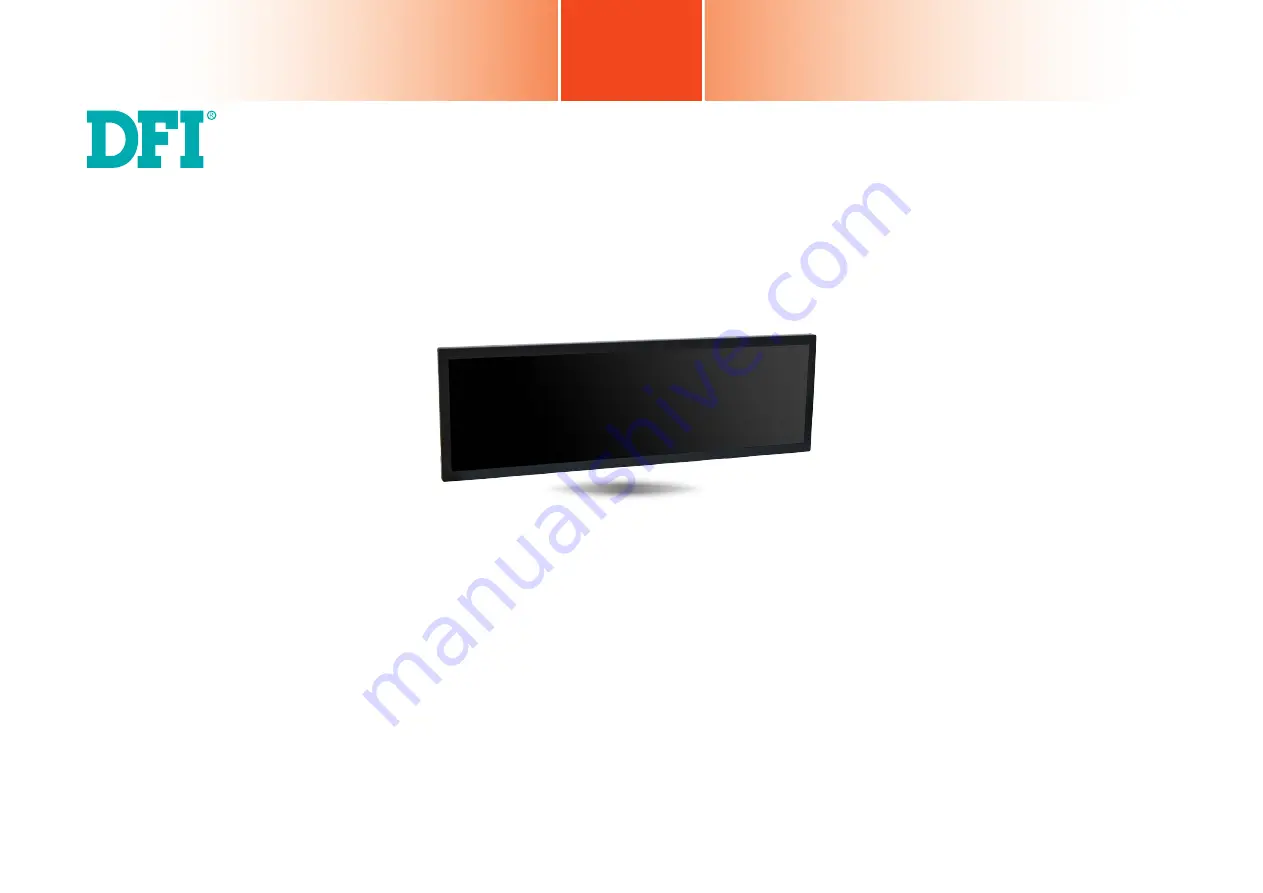
Chapter 1 Introduction
BPC 370/420-BW
TFT-LCD Bar Type Panel PC
User’s Manual
A-475-M-2005
Страница 1: ...www dfi com 1 Chapter 1 Introduction BPC 370 420 BW TFT LCD Bar Type Panel PC User s Manual A 475 M 2005...
Страница 2: ...owners FCC and DOC Statement on Class A This equipment has been tested and found to comply with the limits for a Class A digital device pursuant to Part 15 of the FCC rules These limits are designed t...
Страница 3: ...uto Power on Select 13 Backlight Power Select 14 Panel Power Select 14 LVDS Channel and bpp Select 15 Chapter 5 Ports and Connectors 16 Panel I O Ports 16 12V DC in 16 Graphics Interfaces 17 RJ45 LAN...
Страница 4: ...ischarge can damage computer components without causing any signs of physical damage You must take extra care in han dling them to ensure against electrostatic build up 1 To prevent electrostatic buil...
Страница 5: ...if battery incorrectly replaced Replace only with the same or equivalent type recommend by the manufacturer Dispose of used batteries according to local ordinance Keep this system away from humidity...
Страница 6: ...ocessor Intel Pentium Celeron Processor N3000 Family BGA 1170 Intel Pentium Processor N3710 Quad Core 2M Cache 1 6GHz 2 56GHz 6W LAN Two LAN ports COM Two RS 232 422 485 COM ports DB 9 Display interfa...
Страница 7: ...Single Channel DDR3L 1600MHz 4GB DDR3L memory by default LCD and Touch Screen BPC370 37 1920x540 TFT LCD Panel no touch screen BPC420 42 1920x480 70 000 MTBF LED backlight Brightness cd m 700 1000 ava...
Страница 8: ...a local area network USB 3 0 Ports Connect USB 3 0 devices as well as USB 2 0 1 1 devices VGA Connects to the VGA port of a display DP Connects to the DisplayPort of a display COM Ports Connect serial...
Страница 9: ...www dfi com 9 Chapter 1 Introduction Mechanical Dimensions BPC370 BW Chapter 1...
Страница 10: ...www dfi com 10 Chapter 1 Introduction BPC420 BW 311 60 1085 80 1041 70 261 90 680 36 20 78 20 289 Bottom View Top View Left View Right View...
Страница 11: ...test the message Press DEL to run setup will appear on the screen Press the Delete key to enter the AMI BIOS setup utility Installing an Operating System Most operating system software can be installe...
Страница 12: ...re on the rear side of the system board Mini PCIe and mSATA Removing the Chassis Cover Note The system also has a half size Mini PCIe slot that uses PCIe and USB signals The system board is equipped w...
Страница 13: ...Panel Power Select JP8 ME Disable Chassis Intrusion Intel WGI211AT Intel WGI211AT Nuvoton NCT6106D Chrontel CH7517 RT8175A RT8175A RT5041A DC in JP7 2 3 On Clear CMOS Data 3 1 2 JP6 is used to select...
Страница 14: ...RT8175A RT5041A DC in JP10 1 2 On 3 3V default 3 1 2 2 3 On 5V 3 1 2 Panel Power Select JP8 is used to select the power supplied with the LCD panel Important Before powering on the system make sure t...
Страница 15: ...Power on Select JP6 2 1 5 6 Front Panel 1 5 6 2 2 1 39 40 LVDS LCD Panel 1 SATA 0 1 SATA Power SATA 3 0 1 System Fan 1 2 Battery 2 1 20 19 2 1 20 19 COM 1 COM 2 COM 3 COM 4 1 Clear CMOS Data JP7 1 1...
Страница 16: ...cord to this jack In the system the DC in power connector is connected to a power board AC DC open frame 100W that supplies power to the entire system Using a voltage more than the recommended range...
Страница 17: ...t a display device The interface developed by VESA and backwards compatible with VGA DVI and HDMI delivers higher per formance than any other digital interfaces Driver Installation Install the graphic...
Страница 18: ...7 for more information Important If you are using the Wake On USB Keyboard Mouse function for 2 USB ports the 5V_standby power source of your power supply must support 1 5A For 3 or more USB ports the...
Страница 19: ...dvanced menu Super IO Configuration submenu of the BIOS Refer to Chapter 7 for more information Pins RS 232 RS 422 RS 485 1 DCD_1 TD_1 RD_1 2 DSR_1 3 RD_1 DTR_1 DCD_1 4 RTS_1 5 TD_1 DCD_1 6 CTS_1 7 DT...
Страница 20: ...10 GND Front Audio Connector Front Audio Front Audio The front audio connector allows you to connect the line out and mic in jacks at the front panel of your system In the system the front audio conn...
Страница 21: ...ll blink every second When the system is in the S3 STR Suspend To RAM state it will blink every 4 seconds Pin Pin Assignment Pin Pin Assignment HDD LED 6 HDD_LED RESET SW 5 Reset Button 3 GND 3 GND PW...
Страница 22: ...nnector and the other end to your Serial ATA device BIOS Setting Configure the Serial ATA drive in the Advanced menu SATA Configuration submenu of the BIOS Refer to Chapter 7 for more information Feat...
Страница 23: ...DS_Out3 Odd_3 4 LVDS_Out7 Even_3 5 LVDS_Out3 Odd_3 6 LVDS_Out7 Even_3 7 GND 8 GND 9 LVDS_Out2 Odd_2 10 LVDS_Out6 Even_2 11 LVDS_Out2 Odd_2 12 LVDS_Out6 Even_2 13 GND 14 GND 15 LVDS_Out1 Odd_1 16 LVDS_...
Страница 24: ...the BIOS dis plays the current speed of the cooling fans Refer to Chapter 7 for more information Expansion Slot Mini PCI Express Slot half size The Mini PCIe socket supports PCIe x1 and USB2 0 signals...
Страница 25: ...er SMBus Connector SMBus Chassis Intrusion Connector The board supports the chassis intrusion detection function Connect the chassis intrusion sensor cable from the chassis to this connector When the...
Страница 26: ...y It is an auxiliary source of power when the main power is shut off Safety Measures Danger of explosion if battery incorrectly replaced Replace only with the same or equivalent type recommend by the...
Страница 27: ...resemble the actual one These illustrations are for reference only 2 The VESA mount kit is not included in the product package The VESA mount specifications for this device is 400 x 200 mm Please use...
Страница 28: ...stem to run After you power up the system the BIOS message appears on the screen and the memory count begins After the memory test the message Press DEL to run setup will appear on the screen If the m...
Страница 29: ...n Processor Type CPU Speed CPUID L1 Data Cache L1 Instruction Cache L2 RAM L3 Cache Number of Processors Microcode Revision Total Memory System Memory Speed SODIMM 0 TXE FW Version System Time System...
Страница 30: ...eH20 Setup Utility Rev 5 0 CPU Configuration This section configures the CPU Intel SpeedStep Enable or disable the Enhanced Intel SpeedStep Technology which helps optimize the balance between system s...
Страница 31: ...e that this option is only shown if the Boot type is set to Dual or UEFI Integrated Graphics Device Enable or disable the IGD function Boot Display Video Configuration Primary Display Integrated Graph...
Страница 32: ...io Controller Set to enable or disable the onboard Azalia controller Disabled Azalia will be unconditionally disabled Enabled Azalia will be unconditionally enabled Control Detection of the Azalia dev...
Страница 33: ...xit Select Item Enter Select SubMenu F10 Save and Exit InsydeH20 Setup Utility Rev 5 0 Enabled AHCI Not Installed Not Installed SATA Controller Enable or disable the Serial ATA controller s HDC Config...
Страница 34: ...Item F5 F6 Change Values F9 Setup Defaults Esc Exit Select Item Enter Select SubMenu F10 Save and Exit InsydeH20 Setup Utility Rev 5 0 Enabled Gen2 Configure PCIe Speed CHV A1always with Gen1 Speed PC...
Страница 35: ...ure the settings of each serial port Disable Disable this serial port Enable Enable this serial port Type Choose RS232 RS422 RS485 Peer to Peer for the serial port type for COM port 1 and COM port 2 C...
Страница 36: ...e case open function AC Power Loss Set the AC power loss to Always off or Always on When set to Always off the sys tem s status will be power off after power restoration from an AC power loss event Wh...
Страница 37: ...5 F6 Change Values F9 Setup Defaults Esc Exit Select Item Enter Select SubMenu F10 Save and Exit InsydeH20 Setup Utility Security Boot Exit Rev 5 0 TPM 2 0 FTPM Enabled UnOwned Available No Operation...
Страница 38: ...ock OS Selection Numlock Boot Type PXE Boot to LAN USB Boot Main Advanced F1 Help Select Item F5 F6 Change Values F9 Setup Defaults Esc Exit Select Item Enter Select SubMenu F10 Save and Exit InsydeH2...
Страница 39: ...ed This auto execu tion file will bring you directly to the flash utility menu soon after system boots up and finishes running the boot files in your boot disk Information Please do not remove the AC...
Страница 40: ...software applications Insert the CD into a CD ROM drive The auto run screen Mainboard Utility CD will appear If the Autorun does not automatically start please go to the root directory of the CD and...
Страница 41: ...follow these steps 1 Setup is now ready to install the graphics driver Click Next By default the Automatically run WinSAT and enable the Windows Aero desktop theme is enabled With this is enabled and...
Страница 42: ...mputer now and then click Finish Restarting the system will allow the new software installation to take effect 1 Setup is now ready to install the audio driver Click Next 2 Follow the rest of the step...
Страница 43: ...is preparing to install the driver Click Next to continue 2 Click I accept the terms in the license agreement if you accept the agreement and then click Next 3 Select the program features you want ins...
Страница 44: ...er To install this driver follow these steps 1 Setup is ready to install the driver Click Next to continue 4 After the installation is complete click Finish 3 The step displays the installing status i...
Страница 45: ...ollow these steps 2 Read the license agreement and then click Yes 1 Setup is ready to install the driver Click Next to continue 3 Go through the readme docu ment for more installation tips and then cl...
Страница 46: ...then click Next Serial IO Driver For Windows 8 1 and Windows 10 To install the driver follow these steps 1 Setup is ready to install the driver Click Next to continue 2 Read the license agreement care...
Страница 47: ...ftware Kernel Mode Driver Framework For Windows 7 only To install this update follow these steps 1 Click Yes to install the update 2 The update is being installed now 3 Click Restart Now to restart yo...
Страница 48: ...optional To install this driver follow these steps 2 Read the license agreement and click Yes and follow the on screen instructions for the rest of the installation process 1 Setup is preparing the i...
Страница 49: ...utility follow these steps 1 The setup program is preparing to install the driver 2 The setup program is now ready to install the utility Click Next 3 Click I accept the terms in the license agreemen...
Страница 50: ...d Software 7 TPM requires installing the Micro soft Visual C package prior to installing the utility Click Install 8 The setup program is currently installing the Microsoft Visual C package 9 Click Fi...