Page 19
Printing version 2.6
•JUL2017
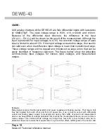
measurement device need to be directly connected. That way we eliminate common-mode voltage.
On DEWE-43 this connection is possible over connector GND wire or over “Common GND”
receptacle on the housing.
Counter and digital inputs:
The DEWE-43 is suited with synchronous 32-bit advanced counter and digital
inputs. In addition to the basic counter function like simple event counting,
up/down counting and gated event counting also period time, pulse width, two-
edge separation, frequency and all encoder measurements are supported. All
counter inputs can also be used as digital inputs. In addition to the basic counter
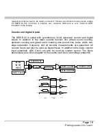
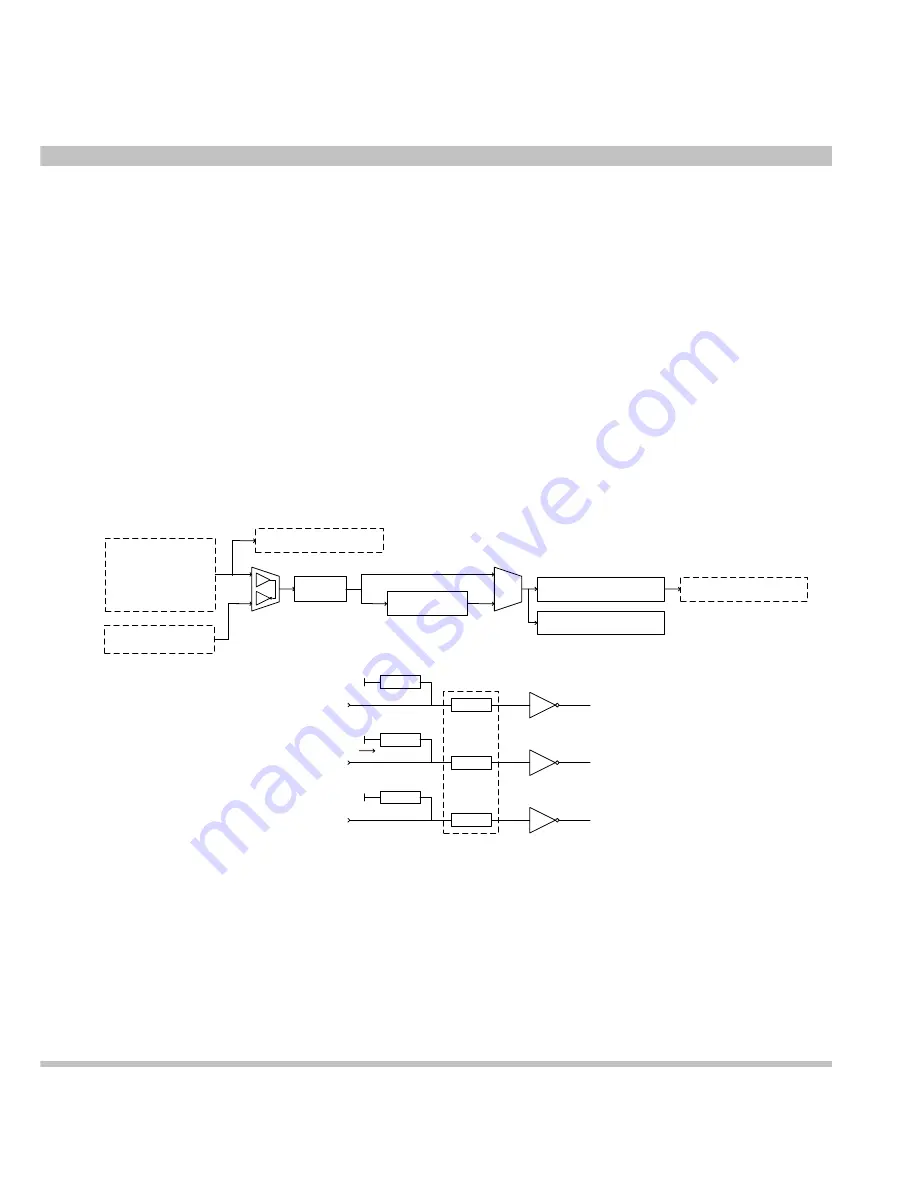
input selections, ADC Clock can also be used as counter source. The figure
bellow shows the block diagram of the counter and input overvoltage protection.
Filter
Decoder
Main Counter
Sub Counter
IN0/A
IN1/B
IN2/Z
ADC Clock
Counter Out
Digital Out
+5V
IN0/A
+5V
IN1/B
+5V
IN2/Z
Pull-up
resistor
Overvoltage
protectio
Buffer


