


ENGLISH
60
2. Slide it into the handle until the battery pack is
firmly seated in the tool and ensure that it does
not disengage.
TO REMOVE THE BATTERY PACK FROM THE TOOL
1. Press the battery release button (o) and firmly
pull the battery pack out of the tool handle.
2. Insert battery pack into the charger as
described in the charger section of this manual.
FUEL GAUGE BATTERY PACKS (FIG. 2)
Some D
E
WALT battery packs include a fuel gauge
which consists of three green LED lights that
indicate the level of charge remaining in the battery
pack.
To actuate the fuel gauge, press and hold the fuel
gauge button (p). A combination of the three green
LED lights will illuminate designating the level of
charge left. When the level of charge in the battery
is below the usable limit, the fuel gauge will not
illuminate and the battery will need to be recharged.
NOTE:
The fuel gauge is only an indication of the
charge left on the battery pack. It does not indicate
tool functionality and is subject to variation based
on product components, temperature and end-user
application.
Attaching Side Handle (fi g. 1)
WARNING:
Before using the tool,
check that the handle is tightened
securely.
WARNING:
The side handle should
always be used to maintain control of
the tool at all times.
Screw the side handle (e) tightly into one of the holes
on either side of the gear case.
To improve user comfort, the gear case will rotate
90° for cutting operations.
Rotating the Gear Case (fi g. 1)
1. Remove the four corner screws attaching the
gear case to motor housing.
2. Without separating the gear case from motor
housing, rotate the gear case head to desired
position.
NOTE:
If the gear case and motor housing become
separated by more than 1/8" (3.17 mm), the
tool must be serviced and re-assembled by an
authorised D
E
WALT service centre. Failure to have
the tool serviced may cause brush, motor and
bearing failure.
3. Reinstall screws to attach the gear case to the
motor housing. Tighten screws to 20 in.-lbs.
torque. Overtightening could cause screws to
strip.
Mounting and Removing the Guard
(fi g. 3)
WARNING: To reduce the risk
of serious personal injury, turn
tool off and disconnect tool from
power source before making any
adjustments or removing/installing
attachments or accessories.
Before
reconnecting the tool, depress and
release the trigger switch to ensure that
the tool is off.
CAUTION:
Guards must be used with
this grinder.
When using the DCG412 grinder for cutting
metal or masonry a Type 1 guard MUST be used.
Type 1 guards are available at extra cost from
D
E
WALT distributors.
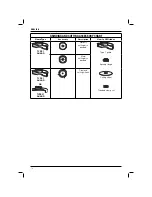
NOTE:
Please refer to the
Grinding and Cutting
Accessory Chart
at the end of this section to
see other accessories that can be used with these
grinders.
1. Place the tool on a table, spindle (d) up.
2. Open the guard latch (k), and align the lugs (l)
on the guard with the slots on the gear
case (m).
3. Push the guard down until the guard lugs
engage and rotate freely in the groove on the
gear case hub.
4. With the guard latch open, rotate the guard (i)
into the desired working position.
5. Close the guard latch to secure the guard on
the gear case.
CAUTION:
If the guard cannot be
tightened by the adjusting screw (n), do
not use the tool. To reduce the risk of
personal injury, take the tool and guard
to a service centre to repair or replace
the guard.
NOTICE:
Do not tighten the adjusting
screw (n) with the clamp lever in the
open position. Undetectable damage
to the guard or the mounting hub may
result.
NOTE:
Edge grinding and cutting can be performed
with Type 27 wheels designed and specified for this
purpose; 6.35 mm (1/4") thick wheels are designed
for surface grinding while 3.17 mm (1/8") wheels are
designed for edge grinding.


