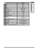
This value is a tool related characteristic and does not represent
the influence on the hand-arm system when using the tool. An
influence on the hand-arm system when using the tool will
depend for example on the gripping force, the contact force,
the working direction, the adjustment of the compressed air
supply, the work piece, the work piece support, etc.
MAINTENANCE INTERVALS
Maintenance intervals for the tools can vary depending
upon the environment the tool is being operated in, the
application it is being used for and the volume of nails that
are being driven. For example, if it is being used in dirty and
dusty conditions for high volume nailing, maintenance will
be required more frequently rather than in clean conditions
with low volumes of nails.
The chart that follows has been produced as a guide to help
you establish the maintenance intervals for the tools. If you
experience an excessive build up of debris within the tool
between cleans, reduce the maintenance intervals. If the
tool does not require cleaning within the schedule you have
established, then you may be able to extend the maintenance
intervals. If you have any questions regarding the above
please contact your local distributor for help and advice.
Maintenance Intervals
Number of Days Between
Maintenance Operations
Operating Environment
Very dirty & dusty
3-4
3-4
3-4
3-4
3-4
Dusty
10-14
10-14
10-14
3-4
3-4
Moderate
30-45
30-45
30-45
10-14
10-14
Clean
45-60
45-60
45-60
30-45
30-45
1
2
4
6
8+
Weekly Nail Usage [x1000]
FILTER CLEANING
When working on the tools, do not lose any parts of the
disassembled tool and use only genuine
D
e
WALT
parts to
ensure proper tool operation and safety.
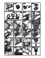
1. Before cleaning, check that the tool has cooled down
completely, and then remove all nails, the fuel cell and
the battery from the tool (Fig. 21).
2. Remove the filter cover using a flat screwdriver (Fig. 22)
and remove the filter (Fig. 23).
3. Remove the dust and rubbish from the filter with cleaner.
Ensure that the filter is dry and free from contamination
(Fig. 24). Replace the filter and filter cover. If the filter is
damaged, replace the filter with a new one.
4. Always carry out 5-10 test cycles of the tool on waste
material before using on a finished surface to expel any
cleaning material residue.
CLEANING & LUBRICATION
Make sure that you have read and understood all safety
warnings and cleaning procedures before attempting to
operate or clean this tool. Failure to do so may result in
serious injury.
WARNING
: Make sure that the 4 hex socket head bolts are
securely attached to the cylinder head before operating the
tool. Loose or missing bolts may cause leakage of burning
gases causing injury to the user and damage to the tool
and property.
1. Before cleaning, check that the tool has cooled down
completely, and then remove all nails, the fuel cell and
the battery from the tool (Fig. 21).
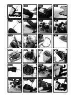
2. Using a 4mm hex key, remove and retain the hex socket
head bolts (Fig. 25).
3. Remove the top cover (Fig. 26).
4. Disconnect the motor lead (Fig. 27) and unplug the spark
plug connection from the spark plug (Fig. 28).
5. Gently lift the cylinder head away from the combustion
chamber (Fig. 29).
6. Ensuring you do not damage the fan blades, carefully
remove the o-ring from the fan (Fig. 30).
7. Using a dry cloth, clean and remove all deposits from the
o-ring. Inspect the O-ring for damage and if necessary,
replace it (Fig. 31).
8. Clean the cylinder head using brake cleaner, paying
particular attention to the spark plug (Fig. 32). A small
brush may be useful to help release some debris. You
may need to repeat this 2 or 3 times until clean.
9. Replace the o-ring on to the cylinder head. Lubricate the
o-ring using
D
e
WALT
gas nailer lubricant (Fig. 33).
10.
Spray brake cleaner into the cylinder to loosen
any residue.
11. Using a blunt instrument (e.g. a screwdriver handle),
push down the piston (Fig. 34).
12. Spray brake cleaner into the combustion chamber and the
chamber head. You may need to do this 2 or 3 times using
a small brush to loosen some of the more stubborn residue
(Fig. 35). Wipe clean any remaining residue (Fig. 36)
16
Содержание DGN9033-XJ
Страница 2: ...DGN9033 XJ ...
Страница 4: ...3 ...

