


DIM D*
INNER FACE OF
DOOR SHOWN
TOP OF DOOR
FOR EASE OF ASSEMBLY,
DOOR MAY BE PLACED ON
SAWHORSES
A
B
C
D
E
F
G
H
J
1
2
TOP
BOTTOM
Rod MUST be
oriented as
shown with
hole A at top
HOLE
2
HOLE
B
C
B
E
F
G
H
J
Rod p/n
104172-1
Rod p/n
104187
Align rod holes
for
DIM B
dimension
of:
2
1
1
1
1
1
1
1
1
D
C
D
2
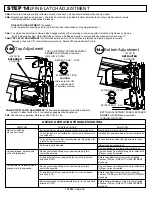
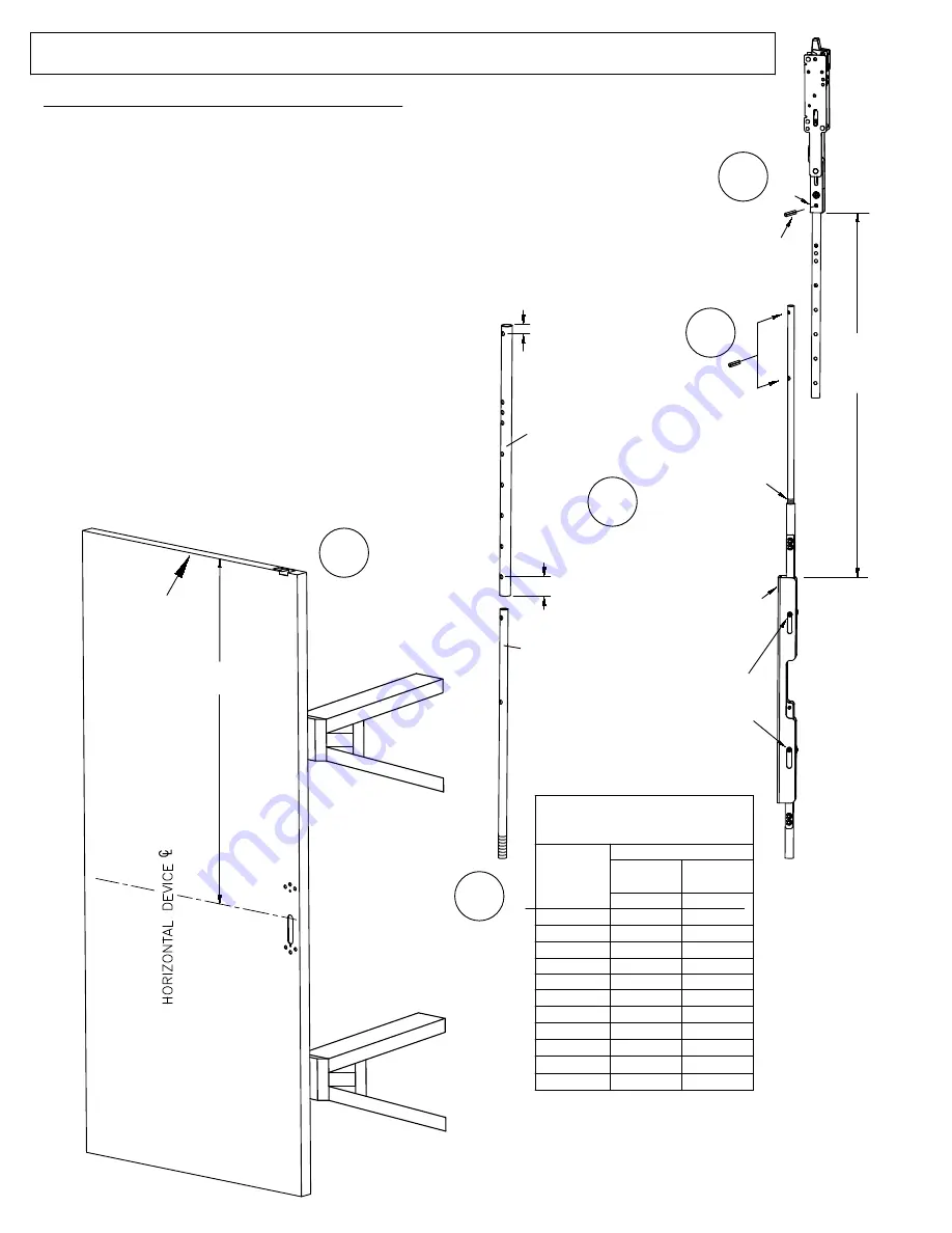
4a.
Align hole A in rod 104187 with hole in top latch as shown at right & tap the 13/16" long pin
into latch hole.
4b.
Measure
DIM B
as shown below.
4c.
Use chart to determine pinning location of rods 104187 & 104172-1.
Round
DIM B
to nearest value in chart.
If more than 3/4" different from one of these chart values, drill a .189 (#12 drill bit)
diameter hole halfway between the 2 holes nearest to the measured
DIM B
and use this hole as pinning hole in next step.
4d.
Insert 104172-1 rod into 104187 rod & line up appropriate
pinning holes (from chart)
on both rods and tap in the 1/2" long pin to secure.
4e
. Calculate
DIM D
:
(
DIM D
= measured
DIM B
minus 15 7/8")
Thread the assembled rods/latch into the centerlift
mechanism assembly as shown at right until
DIM D
is
achieved (within 1/16").
13/16" long
spring pin
p/n 105296
1/2" long
spring pin
p/n 103423
TOP ROD
pinning locations
A
P/N 104187
P/N 104172-1
39-7/8"
40-7/8"
43-7/8"
44-7/8"
45-7/8"
47-7/8"
49-7/8"
51-7/8"
53-7/8"
55-7/8"
41-7/8"
*NOTE: SLOTS
MUST
BE IN
POSITION SHOWN
(SCREWS AT THE TOP)
DURING ADJUSTMENT
Adjust length here
1/2" MINIMUM
thread engagement
required
End marked
TOP
1
2
or
Note: If the combination of holes used
is 2B or 2C, cut off approximately 2"
from the UNTHREADED end of rod 104172-1
(see note
below)
DIM B
104948 Page 8
4b
4e
4d
4a
4c
11/32 REF.
STEP 4:
TOP ROD ASSEMBLY & INITIAL ADJUSTMENT
For 6'-8" (80") to 8'-0" (96") Door
29/32 REF.