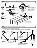
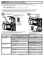
Detex ADVANTEX 70 Series Скачать руководство пользователя страница 18

104948  Page 18

STEP 14:


FINE LATCH ADJUSTMENT

14a.

 Ensure that latches are fully retracted. Gently close door. Latches should extend when door is closed.

14b.

 Depress pushpad and open door. Top latch should clear top strike & bottom bolt should not drag. Latches should remain

         in retracted position with pushpad released.

         FINE LATCH ADJUSTMENT

 (if needed)

14c.

 Top strike fine adjustment: Adjust strike engagement by either retaining or removing shim. Adjust door tightness by moving

          insert to desired position. Note that strike pocket can be flipped around to achieve additional adjustment (see step 11).

14d: 

TOP LATCH ADJUSTMENT:

 With latches extended, turn CCW until the top latchbolt projection begins to visually

          decrease, then turn CW until latchbolt projects fully. Rotate CW one additional full turn.

Bottom Adjustment

TOP ADJUSTMENT SCREW EXPOSED

ADJUST

 with flat blade screwdriver

(PUSH IN & TURN)

Top Adjustment

DEVICE OPERATION TROUBLESHOOTING

Device not latching

when door closes

Latches release, but pushpad

will not fully depress

Latches are not releasing when
pushpad is fully depressed

Bottom bolt is not properly aligned with bottom strike hole.

Top strike insert is not installed or not correctly aligned with
the holdback.

Through fasteners for trim (if applicable) are interfering with

internal centerlift assembly.

Rods improperly adjusted

Device centercase lift finger not inserted properly into

centerlift assembly.

Top adjustment screw is adjusted too far in the retracted
direction (CCW).

Device centercase lift finger not inserted properly into

centerlift assembly.

Top adjustment screw is adjusted too far in the extended
direction (CW).

Bottom adjustment screw is adjusted too far in the extended

direction (CCW).

Modify bottom strike hole for fit.

Install and/or position strike insert per instructions.

Loosen and re-position through screws to clear.

Adjust rods per instructions.

Remove device and re-install per instructions.

Remove device from backplate and re-install with
lift finger correctly inserted.

Rotate top adjustment screw in the extended

direction (CW) per FINE LATCH ADJUSTMENT

procedure.

Remove device from backplate and re-install with
lift finger correctly inserted.

Rotate top adjustment screw in the retracted

direction (CCW) per FINE LATCH ADJUSTMENT

procedure.

Rotate bottom adjustment screw in the retracted

direction (CW) per FINE LATCH ADJUSTMENT

procedure.

                          SOLUTION

         POSSIBLE CAUSE

SYMPTOM

BOTTOM ADJUSTMENT SCREW EXPOSED

ADJUST 

with flat blade screwdriver

(PUSH IN AND TURN)

EXTEND BOLT (CCW)

RETRACT BOLT  (CW)

14e:


BOTTOM LATCH ADJUSTMENT:

 With pushpad depressed (retracted position),

         extend or retract bottom bolt  to desired engagement and clearance.

14f.

 Check device operation. Reference STEP 14a & 14b.

14d

14e

LATCH IN

EXTENDED

POSITION

LATCH IN

RETRACTED

POSITION

CAUTION:

If turned too far CW,

you will lose sight

of adjustment screw

EXTEND BOLT (CW)

RETRACT BOLT  (CCW)

Содержание ADVANTEX 70 Series

Страница 1: ...ial adjustment 10 Step 6 Visual alignment check 11 Step 7 Install top latch mounting bracket 12 Step 8 Insert rod latch centerlift assembly into door 12 Step 9 Secure rod latch centerlift assembly to door 13 Step 10 Verify centerlift mechanism operation 14 Step 11 Hang door assemble device to door 15 Check device for clearance 15 Install mortise cylinder 16 Step 12 Install top strike 17 Step 13 In...

Страница 2: ... cam required See Mortise cylinder installation page Your particular part or configuration may not be shown Contact Detex technical support at 800 729 3839 option 2 18 104948 Page 2 Device Parts Breakdown View 3b 3a 3c 4 4 5 11 6 12 7 1KIT 19 2 8 1A 18 16 9 10 14 15 13 20 13 3d 3KIT 3d 17C 17E 17A 17B 17 KIT 17F 17D or or ...

Страница 3: ...1 Spring pin 3 16 x 5 8 top and bottom rod device only 101607 Center lift mechanism assembly Top ONLY 1KIT 104111 13 104111 14 Centercase CVR Wide LHR Centercase CVR Wide RHR 1A Mounting plate Wide CVR BP13 Use with 03 trim 104171 2 Mounting plate Wide CVR BP11 Use with 08 09 lever trim 104171 1 2 Endcap bracket for EC1 ramped endcap w battery holder 101093 Endcap bracket for EC2 flush endcap w o ...

Страница 4: ...2 PPH P N 12403 1 14 x 1 PPHS P N PP 5183 108 Used to install backplate endcap bracket to door Drill Bit 3 16 pilot hole x 1 deep ALTERNATE SCREW Used with sex bolts or lever trim 2 plus door Drill Bit 7 or 13 64 10 x 1 PFHU P N 100109 10 32 x 1 2 PFH P N PP 5802 308 10 24 x 1 2 PFHU P N 100112 108 Used to install bracket to bottom assembly and top latch Used to install top latch to top of door Fo...

Страница 5: ...SEX NUTS CAN BE PURCHASED SEPARATELY 104948 Page 5 RHR DOOR INSIDE FACE LHR DOOR INSIDE FACE FINISHED FLOOR FINISHED FLOOR X Door Must Swing Freely Door Must Not be Warped Door Must Not Bind Door Must Not Sag Door Skin Reinforcement X X Stile width X Blind Rivet Nut Doors and frames with walls having a structural thickness metal skin plus reinforcement to engage less than 3 full screw threads are ...

Страница 6: ...T Drill 5 16 diameter x 1 8 deep 3 places clearance holes WRAP PREP PREP door before installing wrap A rubber mallet can be used for installing wrap INSTALL wrap per manufacturer s instructions FOR F70 F71 FIRE RATED APPLICATIONS ONLY FOR NON FIRE SKIP TO STEP 3 INSTALL Wrap MARK 3 holes REMOVE WRAP DRILL 3 CLEARANCE holes 5 16 dia x 1 8 deep RE INSTALL Wrap DOOR PREP Use WRAP to mark holes 2a 2b ...

Страница 7: ...T2331 T2335 OR T2338 ON DETEX WEBSITE DETAIL D DOOR TOP MACHINING TOP STRIKE FRAME PREP if not already prepped DOOR OPEN DIRECTION Door frame header Top strike template Template 105299 DOOR OPEN DIRECTION ALIGN template with latch and device vertical centerline DEVICE VERTICAL PRESS template against frame stop and header 7 32 DIA HOLE 5 16 DIA COUNTERSINK Each hole C L C L C L STEP 3 DOOR PREP for...

Страница 8: ...ng hole in next step 4d Insert 104172 1 rod into 104187 rod line up appropriate pinning holes from chart on both rods and tap in the 1 2 long pin to secure 4e Calculate DIM D DIM D measured DIM B minus 15 7 8 Thread the assembled rods latch into the centerlift mechanism assembly as shown at right until DIM D is achieved within 1 16 13 16 long spring pin p n 105296 1 2 long spring pin p n 103423 TO...

Страница 9: ... B and use this hole as pinning hole in next step 4d Insert 104172 2 rod into 105097 rod line up appropriate pinning holes from chart on both rods and tap in the 1 2 long pin to secure 4e Calculate DIM D DIM D measured DIM B minus 15 7 8 Thread the assembled rods latch into the centerlift mechanism assembly as shown at right until DIM D is achieved within 1 16 13 16 long spring pin p n 105296 1 2 ...

Страница 10: ...ne dimension from 38 and measure up this distance from hole V Mark and drill 189 diameter hole 12 drill If DIM A is more than 41 1 2 from floor call customer service at 1 800 729 3839 for assistance Note If hole V or W is used or if new hole is drilled closer to threaded end trim off UNTHREADED end of rod as needed to allow rod to slide into bottom bolt far enough to pin 5b DIM C is the target len...

Страница 11: ...n Hold top rod in place and push top latch case towards device until latchbolt is fully retracted 6c Mounting holes for centerlift should line up with mounting holes in door and top and bottom latches should be in position shown If not go back to steps 3 4 and verify rod length dimensions C L HORIZONTAL DEVICE 3 8 from top of door to latch body STEP 6 VISUAL ALIGNMENT CHECK 6c 6a 6b ...

Страница 12: ...to maintain assembly orientation See detailed view ATTACH top latch brackets as shown below Three screws required for each bracket This side for RHR This side for LHR STEP 7 ATTACH TOP LATCH MOUNTING BRACKETS STEP 8 INSERT ROD LATCH CENTERLIFT ASSEMBLY INTO DOOR 8a 8b INSTALL bracket with 3 screws INSTALL bracket with 3 screws 105985 1 105985 2 10 24 x 5 16 10 24 x 5 16 USE included Loctite USE in...

Страница 13: ...s 9d Attach back plate to centerlift mechanism with two screws DO NOT OVERTIGHTEN Assembly hint Assemble one screw loosely without backplate then add second screw through backplate Remove first screw align backplate and then re install first screw INSTALL bracket with 3 screws STEP 9 SECURE ROD LATCH CENTERLIFT ASSEMBLY TO DOOR 9a 9b 9c 9d INSTALL backplate with 2 screws MARK DRILL 29 drill x 3 4 ...

Страница 14: ...on slot can travel fully to the retracted position Go back to STEP 4 and correct Bottom bolt drag check With top latch in retracted position check to ensure that bottom bolt is not extending from bottom of door a distance greater than the bottom gap at finished floor minus the threshold height if threshold is used If it is then bottom rod is too long Go back to STEP 5 and correct Upon completion r...

Страница 15: ...before cutting Minimum Fillerplate Length SLIDE endcap assembly onto extrusion CAUTION CHECKING FOR DEVICE CLEARANCE Cut Off procedure if required Type Length L 2 1 2 LD 3 HD CD For aluminum Advantex finish cutdown applications After cutting the baseplate extrusion can be reversed to place the cut end inside the head cover To do so loosen the setscrew inside the aluminum baseplate extrusion and sl...

Страница 16: ...e 2 screws to the rest of the assembly NOTE The key should easily turn in both directions f Rotate key counterclockwise g Assembly complete Continue with Panic Hardware instruction Mortise Cylinder with standard Yale cam required 715 313 Cylinder nut socket p n 103779 sold separately 11h LEVEL device before installing endcap bracket ENSURE that device does not require cutting see Step 11g on next ...

Страница 17: ...r stop Door frame header 104948 Page 17 NOTE 1 If using threshold drill 5 8 hole Door stop side TILT strike pocket to fit into cutout Finished strike installation view Door frame header Top strike pocket Shim Strike insert 13a 13c 13b STEP 12 TOP STRIKE INSTALLATION STEP 13 BOTTOM STRIKE INSTALLATION Disregard if TRO device is being installed INSTALL top strike strike insert with 4 screws 10 32 x ...

Страница 18: ...ed Device centercase lift finger not inserted properly into centerlift assembly Top adjustment screw is adjusted too far in the retracted direction CCW Device centercase lift finger not inserted properly into centerlift assembly Top adjustment screw is adjusted too far in the extended direction CW Bottom adjustment screw is adjusted too far in the extended direction CCW Modify bottom strike hole f...

Страница 19: ...S INSTALL endcap with 2 screws INSTALL cover with 4 screws 10 32 x 5 16 6 32 x 3 8 Auxiliary bolt assembly STEP 16 INSTALL AUXILIARY FIRE BOLT F71 ONLY See Auxiliary Bolt instructions p n 104934 included with kit EC2 flush endcap shown 15a 15b ...

Страница 20: ... 4 20 kits are available in 3 finishes Brushed Brass BHMA 606 p n 105274 2 Oil Rubbed Bronze BHMA 613 p n 105274 25 Stainless Steel BHMA 630 p n 105274 9 Catalog No SN3 uses screws in hardware kit Tamper Kit Security Kit Catalog Part SSK5 Security Screws Security Pin TORX Bits provided ...

Отзывы: