DS7400Xi-AT (Ver. 3+) Reference Guide Copyright © 1995-2000 Detection Systems, Inc. Page 81
16.0
RF (Wireless) Programming Guide
16.1
Zone Programming
Before installing a RF (Wireless) device, its address and other
information must be programmed into the control panel. Perform
the following:
• Addresses 0166 “Multiplex Zone Type” and 0168 “Receiver
Programming” should be programmed prior to zone
programming.
• Program the control panel.
- Refer to Section 11.2-11.4, Zone Programming.
This section allows you to define the RF (Wireless) Zone’s
address (zone number), its type (always a single input zone,
selection 0), which zone or output function it will follow (1-15)
and its partition (1-8). The Zone Functions for RF zones must
always be set for “Alarm on Short”. DO NOT program the zone
function for “Trouble on Short”.
For example:Program zone 9 to be a single zone input device
that follows zone function 1 and is in partition 1.
Procedure:
Enter the programmer’s mode.
Enter address 0026.
Enter the data digits as [0] and [1] followed by the
[#] button.
Enter address 1252.
Enter the data digits as [0] and [0] followed by the
[#] button.
Exit the programmer’s mode.
• Once the zone programming is done, you are ready to program
the RF devices. Perform the following:
- Enter the programmer’s mode.
Do this by entering the programmers code followed by [#] [0] .
You may exit the programming mode at any time by
pressing the [*] key for two seconds. If no keystrokes are
detected for four minutes, the panel will automatically exit
the programmer’s mode.
- Enter the RF programming mode.
Do this by entering [9] [9] [9] [0] followed by the [#] button.
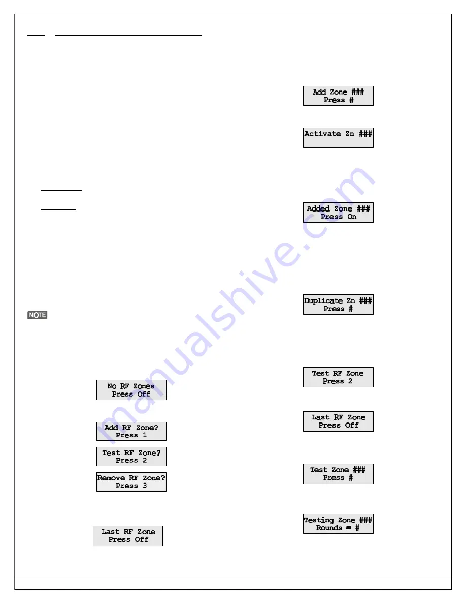
- If no RF zone addresses have been programmed into the panel
the following message will appear:
- If RF zone addresses have been programmed into the panel,
the RF Installer’s Menu will appear:
• Select “Add RF Zone” by pressing the [1] key.
• If all of the RF zones have been added, the following message
will appear:
• If zones are ready to be added, the display below will appear.
The zone number shown will be the lowest number zone
available to be added. You may step foreward to other
programmed and ready to be added zones by pressing the [ON]
key on the keypad. If you step through all the zones and the
message “Last RF Zone - Press Off” appears, you may return to
the first available zone for programming by pressing the [On] key.
You cannot step backward through the zones - only forward. You
may exit the programming mode at this time by pressing the [Off]
key.
• When the zone number desired is shown in the display, press
the # key to accept that zone number and display the following:
• At this time, create a Tamper condition at the sensor (or “Test” on
a wireless smoke detector) for that zone number. The system will
confirm acceptance of the zone with a single beep from the keypad.
A three beep error tone from the keypad will indicate that the
zone was not accepted by the system. After acceptance, the
following message will appear on the display:
• Pressing the “On” key at this time will prompt the system to the
next zone ready to be added to the system or display the message
“Last RF Zone Press Off” if there are no zones to be added.
• If the display shows the following message, it indicates that the
sensor code has already been added to the system. The sensor
shown can be removed from the system (see Section 16.3) or
another sensor may be added to the system.
• Pressing the # key will attempt to program the zone again.
• Pressing the “Off” key will exit the Add RF Zone mode.
16.2
Testing RF Zones
From the main menu, select Test RF Zone (selection 2).
• If there are no RF zone addresses programmed into the system
or if the zones have not been “Added”, the display will read:
• If RF zone addresses are programmed into the system and the
sensors have been “Added”, the display will show the first RF
sensor available for testing:
• You may test the zone shown by pressing the [#] key or advance
to another zone by pressing the [On] key. When the zone is tripped
the Rounds value will be displayed:
• The Rounds Value will be displayed as a value of 0-8 with 7-8
being an acceptable value, 5-6 as marginal and 0-4 as
unacceptable levels.
Содержание DS7400Xi-AT
Страница 11: ...DS7400Xi AT Ver 3 Reference Guide Copyright 1995 2000 Detection Systems Inc Page 11 5 0 System Worksheet...
Страница 76: ...DS7400Xi AT Ver 3 Reference Guide Copyright 1995 2000 Detection Systems Inc Page 76 Pager Format Continued...
Страница 78: ...DS7400Xi AT Ver 3 Reference Guide Copyright 1995 2000 Detection Systems Inc Page 78 14 1 SIA Formats Continued...
Страница 79: ...DS7400Xi AT Ver 3 Reference Guide Copyright 1995 2000 Detection Systems Inc Page 79 14 2 CID Formats...
Страница 94: ...DS7400Xi AT Ver 3 Reference Guide Copyright 1995 2000 Detection Systems Inc Page 94 Installation Notes...
Страница 95: ...DS7400Xi AT Ver 3 Reference Guide Copyright 1995 2000 Detection Systems Inc Page 95 Installation Notes...
Страница 96: ...DETECTION SYSTEMS INC...


