3
Product Overview
Page 9
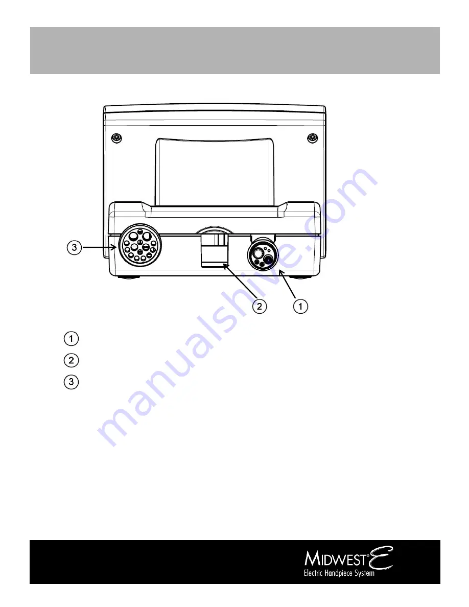
Back Panel
Figure 2
– Back Panel of the Unit
4-hole, 5-hole, or 6-pin Connector
Power Supply Input
Motor Hose Input
Страница 1: ...Doc No 87514 0914 Directions for Use CAUTION US Federal law restricts this device to sale by or on the order of a licensed dental professional...
Страница 2: ...21 8 Endodontic Mode 23 Endodontic Mode Operations 23 9 Cleaning and Maintenance 26 Cleaning 26 Maintenance 26 10 Troubleshooting 27 11 Information on Electromagnetic Compatibility 28 12 Specification...
Страница 3: ...ments intended for cutting shaping filing drilling cleaning and polishing procedures in both general and endodontic dentistry System Contents The Midwest E Electric Handpiece System is comprised of th...
Страница 4: ...ations for Use any other type of use or alteration to the product is prohibited and can lead to personal injury or damage to the product Electric Dental Micromotors generate significantly more power t...
Страница 5: ...nly use files with shafts meeting the requirements of ISO 1797 2 ISO 3630 1 and ISO 3630 2 with a shaft diameter of 0 092 to 0 093 inches Service Using Authorized Personnel Only Supply of spare parts...
Страница 6: ...spect the power cord and the control unit case before use for any damages to the cord ground wire or casing Precautions Avoid Adhesive Labels on the Instrument Tubing Attaching adhesive labels or tape...
Страница 7: ...Humidity Keep dry Temperature range Quantity Transport upright Air pressure Exclusion of Liability Supply of spare parts service and maintenance may only be carried out by authorized personnel DENTSP...
Страница 8: ...oduct Overview Page 8 3 Product Overview Overview of the Unit Figure 1 Overview of the Unit LCD Screen Control Unit Midwest E Motor Power Supply Unit Power Supply Main Cord Motor Hose Installation Bra...
Страница 9: ...3 Product Overview Page 9 Back Panel Figure 2 Back Panel of the Unit 4 hole 5 hole or 6 pin Connector Power Supply Input Motor Hose Input...
Страница 10: ...e the controller unit into the bracket Using the four screws and washers supplied mount the unit to the bracket by aligning the four slots on the bracket base with the four holes on the bottom of the...
Страница 11: ...e 5 below CAUTION Compressed air supply must be clean dry and free from oil per ISO 7494 2 A filter water trap or air dryer may be required Failure to adhere may damage the motor or attachments of the...
Страница 12: ...nnected from the control unit by pulling the connector away from the back of the unit for service and replacement 2 Connect the Midwest E motor to the motor hose tube Lightly coat the O rings on the m...
Страница 13: ...Calibration of foot control working pressure Submenu in the Set up SPEAKER Speaker on off Audio Submenu in the Set up CONTRAST BRIGHTNESS Display contrast brightness setting Submenu in the Set up UP C...
Страница 14: ...2 P3 P4 P1 P2 P3 P4 Memory cell for preparation Main menu TORQUE Torque value setting Main menu E1 to E5 DEMO Demonstration of motor rotation without air connection Set up menu START Start motor Demon...
Страница 15: ...IME Icon AUTO REVERSE FORWARD TIME Icon Figure 11 Setup Mode Menu DEMO Mode Icon Set Up Mode SETUP allows the user to adjust the following Parameters Setting options Factory setting Calibration Foot P...
Страница 16: ...und is heard maximum pressure has now been calibrated to equal 100 After the signal sounds the system will automatically change the icon to MIN meaning the system is ready to calibrate the minimum pre...
Страница 17: ...ndpiece light intensity 2 Pressing the and icons will toggle light intensity 3 Confirm the desired setting by pressing the HANDPIECE LIGHT icon again The saved value will appear inside the icon To Adj...
Страница 18: ...the desired Gear Setting ratio desired 3 Press the GEAR SETTINGS icon again to confirm the setting 4 Repeat the same procedure above for Gear Ratio B To Reset Factory Settings All manual settings can...
Страница 19: ...Safe and Accurate Device Operation by Confirming all input values before use including motor speed in relation to the appropriate handpiece attached torque limits and drill direction Monitoring devic...
Страница 20: ...n on Operating Instructions using PREP mode can be found in Preparation Mode Operations on page 20 Endodontic Mode ENDO For performing Endodontic Procedures information on operating instructions using...
Страница 21: ...ion Mode PREP Mode Icon SPEED Icon HANDPIECE LIGHT Icon DIRECTION OF ROTATION Icons GEAR RATIO Icon PREP MODE MEMORY SETTING Icons Parameter Icons Figure 9 Preparation Mode Menu Screen Table 1 PREP Mo...
Страница 22: ...ustrates the direction of rotation i e clockwise or counter clockwise when the rotary instrument is facing away from the user Storing Settings in Memory 12 Pressing the P1 button and holding it in unt...
Страница 23: ...them as described below This allows one to compile their own preferences to fit their option needs NOTE In Endodontic Mode the light source is set to ON for all presets Endodontic Mode ENDO Mode Icon...
Страница 24: ...SPEED icon when activated the background becomes highlighted 7 Change the speed using the or icons until the speed desired is displayed 8 Confirm by pressing the SPEED icon again the color of the icon...
Страница 25: ...endodontic file the handpiece will stop Auto Reverse When the specified torque value is reached on the endodontic file the handpiece will reverse in direction until the user releases the foot pedal A...
Страница 26: ...exert any pressure on the LCD screen Do not use products containing acetone chlorine or bleach as disinfecting agents on the Control Unit Never immerse the Control Unit in solvent The device is not su...
Страница 27: ...n the back of the unit Error Code ERR 82 Position sensor not connected Check and ensure the motor hose is connected correctly to the control unit per the installation instructions on Page 12 Reset the...
Страница 28: ...oltage 2 kV common mode voltage 1 kV push pull voltage 2 kV common mode voltage The quality of the supply voltage should correspond to that of a typical business or hospital environment Voltage interr...
Страница 29: ...the above conformance level the medical device should be monitored to demonstrate proper function When unusual performance features are observed additional measures may be necessary such as realigning...
Страница 30: ...system Overvoltage category II Pollution degree P2 Device classification of applied part EN 60601 Type B Protection category IP 20 Power Supply Rated voltage 100 240 V AC Rated frequency 50 60 Hz Pow...
Страница 31: ...o 75 Max altitude 2000 m Storage and Transport Conditions PRECAUTION Starting up the medical device after storage in very cold conditions can cause an operational failure of the medical device Very co...
Страница 32: ...L UNIT 875070 POWER SUPPLY CORD 875045 MIDWEST E MOTOR 875055 MIDWEST E MOTOR O RINGS 875060 MIDWEST E MOTOR HOSE CONNECTION O RING 875065 MIDWEST E MOTOR SEAL 875050 DETACHABLE HOSE 875035 DETACHABLE...
Страница 33: ...ll void the warranty There are no warranties express or implied which extend beyond the description of the face hereof DENTSPLY neither assumes nor authorizes any person to assume for it any other lia...