background image

DAEnetIP2

 User Manual
 12 Sep 2013

11.

Appendix 4. Port forwarding - for advanced users

This  appendix  describes  how  to  access  the  

DAEnetIP2  

over   the  Internet.   The 

demonstration is done with router "TP-Link  

TL-WR340G

", but it may be done with 

any other router supporting "Port Forwarding" function. Bellow are given the steps 
you have to go through to make "Port Forwarding".

1. Adjust DAEnetIP2 network ports. These ports are:

SNMP port, by default 161

HTTP port, by default 80

DAEnetIP2 will accept any valid integer number for port >1025 and <65535. Port 

numbers from 0 to 1024 will be accepted as 161. The same is with port 80.

Let's say we would like to adjust for example:

Port 10080 for HTTP

Port 10161 for SNMP

This may easily be done from the DAEnetIP2 web server -> Setup page

2. These ports must be set in the forwarding rules inside the router as it is shown 

on the figure bellow

Figure 33. Port forwarding

The IP address 192.168.1.11 is actually the internal address of the 

DAEnetIP2.

3. Now it is possible to access the 

DAEnetIP2  

from everywhere outside the LAN 

(including over the Internet).

xxx.xxx.xxx.xxx:10080 - is the web server of the module
snmpget -v1 -c 000000000000 xxx.xxx.xxx.xxx:10161 .1.3.6.1.4.1.19865.1.1.1.0 - 

snmp command for accessing the module (get the IP)

xxx.xxx.xxx.xxx - the public IP of the router or it's DNS name.

-

39

Содержание DAEnetIP2

Страница 1: ...DAEnetIP2 User Manual 12 Sep 2013 DAEnetIP2 User Manual Date 12 Sep 2013 Describes the features of DAEnetIP2 with firmware version 4 097 1 ...

Страница 2: ...0 Appendix 3 Install and power on DAEnetIP2 denkovi relay board kit 32 11 Appendix 4 Port forwarding for advanced users 39 12 Appendix 5 Software 40 13 Appendix 6 Software examples 46 14 Appendix 7 HTTP API commands 47 15 Appendix 8 Firmware upgrade 48 16 Appendix 9 Digital I O ports P3 P5 50 17 Appendix 10 Using analog inputs port P6 51 18 Appendix 11 Using analog temperature sensors 52 19 Append...

Страница 3: ...igurable digital I O port 0 3 3VDC Standart protocols ARP IP ICMP ping DHCP Supports snmp v1 snmpset snmpget snmptrap HTTP web server with autorization TFTP for firmware upgrade Ports for SNMP 161 and HTTP 80 can be changed Two MAC addresses protection It can be configured with SNMP requests or web browser Integrated WEB server for all functions parameters access I O lines labels can be changed vi...

Страница 4: ... Link Activity Power On Yes Save I O states Yes DHCP Yes Network parameters IP Mask Default gateway MAC lock protection Yes SNMPv1 Yes snmpget snmpset Read Write Community String Yes Read Only Community String Yes SNMP traps Yes SNMP I O access commands Yes Web server for configuration access Yes TFTP client for remote firmware update Yes Command for TFTP update Web SNMP Yes Enable Disable TFTP up...

Страница 5: ...ol DAEnetIP2 Relay Board PC Power supply Electrical device Figure 1 Example 1 3 2 Data acquisition SNMP Monitoring Software Sensor Sensor Sensor S N M P T r a p S N M P SNMP S N M P DAEnetIP 2 DAEnetIP 2 DAEnetIP 2 SNMP Trap SNMP HTTP Web browser H T T P Figure 2 Example 2 5 ...

Страница 6: ...DAEnetIP2 User Manual 12 Sep 2013 3 3 Watchdog function Figure 3 Example 3 6 ...

Страница 7: ...ty string 000000000000 SNMP RW community string private SNMP Web Access network IP 172 16 100 1 SNMP Web Access network Mask 0 0 0 0 disabled Ping Timeout 6 Restart on incoming ping timeout Disabled Restart on remote IP timeout Disabled Remote monitor IP 172 16 100 1 I O ports settings P3 P5 Outputs Pull Up Pull Down All pull down Pull up down for inputs Enabled Reset I O ports on restart Disabled...

Страница 8: ...meters will be returned back as those in point 4 1 from the current document Figure 4 Loading default settings 1 Turn off the power supply of the device 2 Move the jumper from position 1 to position 2 3 Turn on the power supply of the device 4 Move the jumper from position 2 to position 1 5 Turn off the power supply of the device 6 Turn on the power supply of the device 8 ...

Страница 9: ...DAEnetIP2 User Manual 12 Sep 2013 5 Connectors and ports 5 1 DAEnetIP2 ports Figure 5 DAEnetIP2 ports 9 ...

Страница 10: ...6 Free I O 6 Free Ain 7 7 Free I O 7 Free I O 7 Free Ain 8 8 Free I O 8 Free I O 8 Free Ain 9 GND PWR 3 3V PWR 3 3V Vref PWR 10 GND PWR GND PWR GND PWR Table 4 System port DAEnetIP2 System Port JP6 reserved not used Pin N Bit FUNC Dir 1 3 3V PWR 2 3 3V PWR 3 Reserved 4 Ping Led Out 5 Reserved 6 Target RST Out 7 Reserved 8 Reserved 9 Reserved 10 GND PWR Legend Free the pin is free to be used by use...

Страница 11: ...The browser must support JavaScript There is username and password Basic Authentication The web server has only one session only one user can access the DAEnetIP2 via web at a time The session has timeout 60 seconds if there is not access from the browser After that another user can access the module This is done because of security reasons 11 ...

Страница 12: ...ot be changed 6 1 2 MAC address The MAC address of the module Can not be changed 6 1 3 IP address The IP address of the module 6 1 4 Subnet Mask The subnet mask of the module 6 1 5 Default Gateway The Default gateway of the module SNMP cfgIP 0 cfgNetMask 0 cfgDefGW 0 Web Menu Setup IP address Setup Subnet Mask Setup Default Gateway 12 ...

Страница 13: ... server If there is answer from the DHCP server the DAEnetIP2 accepts immediately the new settings and reconfigures its network interface 6 1 8 MAC filtering DAEnetIP2 has MAC protection This means that if it is enabled it can be accessed from one two MAC addresses For disable the MAC protection the MAC must be 000000000000 SNMP cfgMACLock1 0 cfgMACLock2 0 Web Menu Setup Access MAC address 1 and S...

Страница 14: ... why it must be sent 5 10 ping requests Outgoing ICMP monitoring During outgoing monitoring the DAEnetIP2 module generates ping to the given IP address and expects answer within the given timeframe The request generating is performed several times in minute The both ICMP modes use one shared parameter timeout however they have separate timers Restart Target Device To restart external device via re...

Страница 15: ...f output Ping LED see the i o table description The schematic bellow shows how to connect this pin to LED Figure 8 Connecting Ping LED SNMP Change its bit in cfgNewMode 0 Web Menu Setup Toggle JP6 4 on outgoing ping request Second LED indicator This indicator may show Power ON Ping IN Ping OUT Ping BOTH DHCP valid IP SNMP Change its bit in cfgLED2mode 0 Web Menu Setup Second LED mode 6 1 12 IO Por...

Страница 16: ...C When this option is activated the analog inputs returns the measured value slower but more clear SNMP Change bit DISABLE_ANALOG_FILTER in cfgMode 0 Web Menu Setup Digital filter for ADC 6 1 13 TFTP firmware update DAEnetIP2 has TFTP client for firmware update When the command is initiated the DAEnetIP2 module connects to the TFTP server and starts downloading the firmware version After checking ...

Страница 17: ... command and of course after loading the default settings If however the SNMP access is disabled then the allowing of the WEB server may be done only after hardware loading of the default settings From this section the web port may be changed also The port must be in range from 1025 up to 65535 The attempt to assign port from 1 1024 will be accepted as 80 After setting this parameter the DAEnetIP2...

Страница 18: ...they have been generated The controller generates traps each 2 3 seconds when it is in alarm zone This is because the SNMP trap is UDP based message and the receiving is not guaranteed 6 3 Analog events DAEnetIP2 Analog inputs could be attached to P5 digital output port When analog input is changed the corresponding digital output can react There are 4 modes 6 3 1 Mode Low The output will become 1...

Страница 19: ... used this option allows to be done automatic switch ON of load when the temperature is higher than the threshold HIGH and switch OFF when the temperature is lower than the threshold LOW And it is possible the opposite without INV it is possible heating during low temperatures for instance antennas the output is ON when level is lower than LOW and OFF when the level is higher than HIGH SNMP Changi...

Страница 20: ...netIP2 User Manual 12 Sep 2013 6 5 Port Labels Figure 12 Port Labels From this web page it is possible to change the name for each I O pin Note this is possible to be done only via web and not via snmp 20 ...

Страница 21: ...t Figure 13 Account settings 6 7 Firmware Update This command starts firmware update The DAEnetIP2 will download the firmware file from the TFTP server given in Setup section After that the device will be rebooted 6 8 Reboot Reboots DAEnetIP2 21 ...

Страница 22: ...l setting of IP MASK Gateway must be done via Web Otherwise the DAEnetIP2 module may become not reachable because of the limitation of only one OID accessing per a time via snmp 7 1 Configuration settings Table 5 Configuration settings OID Name Access Description Syntax x 1 1 1 0 cfgIP read write IP Address of DAEnetIP2 module IpAddress x 1 1 2 0 cfgMAC read only MAC address of DAEnetIP2 module Ph...

Страница 23: ...s different bit flags for DAEnetIP2 operating modes SAVE_IOPORTS bit0 PING_LED bit1 PING_TIMEOUT_IORE SET bit2 TFTP_UPDATE bit3 DHCP_CLIENT bit4 MONITOR_TIMEOUT_ RESTART bit5 WEB_SERVER bit6 SWITCH_RESTART bit7 INTEGER 0 25 5 x 1 1 12 0 cfgResetPulse read write fw 4 066 Defines the time ot the RST pulse value 250ms INTEGER 0 32 767 x 1 1 13 0 cfgResetCount read write fw 4 066 Number of consecutive...

Страница 24: ... class allowed to access DAEnetIP2 IpAddress x 1 1 22 0 cfgHTTPport read write fw 4 094 Defines listen port for Web server Allowed values 80 and 1024 INTEGER 0 65 535 x 1 1 23 0 cfgSNMPport read write fw 4 094 Defines listen port for SNMP server Allowed values 161 and 1024 INTEGER 0 65 535 x 1 1 24 0 cfgLED2mode read write fw 4 094 Defines LED2 behaviour INTEGER PowerOn 0 PingIn 1 PingOut 2 PingBo...

Страница 25: ...eshold INTEGER 0 1023 x 1 1 122 3 0 atrPin2Low read write Pin low threshold INTEGER 0 1023 x 1 1 122 4 0 atrPin2High read write Pin high threshold INTEGER 0 1023 x 1 1 122 5 0 atrPin3Low read write Pin low threshold INTEGER 0 1023 x 1 1 122 6 0 atrPin3High read write Pin high threshold INTEGER 0 1023 x 1 1 122 7 0 atrPin4Low read write Pin low threshold INTEGER 0 1023 x 1 1 122 8 0 atrPin4High rea...

Страница 26: ... 1 1 121 4 0 aevPin4 read write Defines reaction on respective P5 output pin when voltage is compared to thresholds INTEGER None 0 Low 1 High 2 LowHigh 3 Acc 4 x 1 1 121 5 0 aevPin5 read write Defines reaction on respective P5 output pin when voltage is compared to thresholds INTEGER None 0 Low 1 High 2 LowHigh 3 Acc 4 x 1 1 121 6 0 aevPin6 read write Defines reaction on respective P5 output pin w...

Страница 27: ...pctrlP3pin4 read write Port3 pin4 data INTEGER High 1 Low 0 x 1 2 1 5 0 pctrlP3pin5 read write Port3 pin5 data INTEGER High 1 Low 0 x 1 2 1 6 0 pctrlP3pin6 read write Port3 pin6 data INTEGER High 1 Low 0 x 1 2 1 7 0 pctrlP3pin7 read write Port3 pin7 data INTEGER High 1 Low 0 x 1 2 1 8 0 pctrlP3pin8 read write Port3 pin8 data INTEGER High 1 Low 0 x 1 2 1 33 0 pctrlP3byte read write I O port data as...

Страница 28: ...s are from 10bit Analog to Digital Converter Table 11 Returned values from ADC OID Name Access Description Syntax x 1 2 3 1 0 pctrlP6pin1 read only ADC Channel 1 INTEGER 0 1023 x 1 2 3 2 0 pctrlP6pin2 read only ADC Channel 2 INTEGER 0 1023 x 1 2 3 3 0 pctrlP6pin3 read only ADC Channel 3 INTEGER 0 1023 x 1 2 3 4 0 pctrlP6pin4 read only ADC Channel 4 INTEGER 0 1023 x 1 2 3 5 0 pctrlP6pin5 read only ...

Страница 29: ...The maximum voltage is 25VDC The optimal voltage is 12VDC The voltage polarity is tip center positive The device does not protection against reverse polarity voltage Other supply voltages than described may damage the device Figure 14 Power supply polarity Figure 15 DAEnetIP2 power supply jack 29 ...

Страница 30: ...ct the DAEnetIP2 device with your computer via UTP crossover cable note that the device does not support AUTO MDIX 2 Supply with voltage in the allowed range For example 12VDC stabilized filtered power source 3 Your initial computer IP should be in the device network So it is recommend to be 172 16 100 1 Change it 4 Open web browser and type 172 16 100 2 default username password are admin admin 5...

Страница 31: ...68 1 2 2 2 Mask 2 3 Gateway usually this is the IP of your router 3 Click submit and wait about 5 seconds 4 Power off the device 5 Now you may disconnect the UTP crossover cable from the DAEnetIP2 and your computer 6 Connect the DAEnetIP2 module and the network router with UTP straight cable 7 Adjust the IP of your computer to be again in the router network 8 Open the web browser and enter the new...

Страница 32: ...th DAEnetIP2 www denkovi com The steps instructions are valid for only for kits with DAEnetIP2 cable relay board from Denkovi Assembly Electronics LTD without matter how many relays is the kit 1 Connect DAEnetIP2 UTP crossover cable if it will be connected to computer or UTP stright through if it will be connected to router Figure 18 Connecting UTP cable to DAEnetIP2 2 Connect the other end of the...

Страница 33: ...kit you should have the DAEnetIP2 connected with the cable If not please contact with us 3 1 Internet Ethernet 16 Channel relay board The relay board is connected to ports P3 and P5 Figure 21 Connecting cable for 16 channel relay board 3 2 Internet Ethernet 8 Channel relay board The relay board is connected to port P5 Figure 22 Connecting cable for 8 channel relay board 33 ...

Страница 34: ...nd P5 8 pins Figure 23 Connecting cable for 2 channel relay board 4 Connect each In labeled wire into the referred screw terminal of the relay board For example In 1 wire goes into Relay 1 In screw terminal In 2 wire goes into Relay 2 screw terminal and so on Figure 24 Connecting In wires into the screw terminals 34 ...

Страница 35: ...cable into the GND screw terminal of the relay board For example bellow it is shown 8 channel relay board The same is for the rest relay boards Figure 25 Connecting the GND wire to the relay board 6 Connecting power supply Figure 26 Plug the power supply jack into DAEnetIP2 35 ...

Страница 36: ... the kit with single power supply source In this case it is 12VDC If you have 24V relay board version then you must use 24VDC single power supply source DAEnetIP2 accept from 7 5V 25V Vcc GND 12VDC GND GND GND From Flat Ribbon Cable IP Controller power jack 12VDC RJ45 GND IN NO C NC INX 120VAC IP Controler Relay Board Relay FLAT RIBBON CABLE Power source Figure 28 Single power supply source 36 ...

Страница 37: ...ill have to make a sum with DAEnetIP2 current consumption relay board current consumption DAEnetIP2 current consumption is 50mA at 12VDC If we have for example 16 channel relay board 12VDC the consumption is 600mA So you will need power supply which can provide more than 600 50 650mA at 12VDC Or 2 supply sources one 50mA and another 600mA at 12VDC You can see the other relay boards current consump...

Страница 38: ...DAEnetIP2 User Manual 12 Sep 2013 Figure 31 Relay board power led is on constantly Figure 32 The kit in working condition The same is for the other kits 38 ...

Страница 39: ...24 will be accepted as 161 The same is with port 80 Let s say we would like to adjust for example Port 10080 for HTTP Port 10161 for SNMP This may easily be done from the DAEnetIP2 web server Setup page 2 These ports must be set in the forwarding rules inside the router as it is shown on the figure bellow Figure 33 Port forwarding The IP address 192 168 1 11 is actually the internal address of the...

Страница 40: ...rojects You can see also what else 3rd parity software is available for DAEnetIP2 on this link http denkovi com page 43 the 3rd parity software for denkovi devices html 12 1 DRM Software Denkovi Relay Manager DRM is universal software for easy controlling all kinds of Denkovi USB VCP and SNMP and TCP IP relay boards It may be used with DAEnetIP2 relay board Figure 34 DRM software Software web page...

Страница 41: ...DAEnetIP2 User Manual 12 Sep 2013 12 2 DAEnetIP2 Manager DAEnetIP2 Manager is configuration utility for Denkovi DAEnetIP2 controller Figure 35 DAEnetIP2 Manager Download link here 41 ...

Страница 42: ...application is offered to extend control of the DAEnetIP2 controller and relay board to your Android phone This application is designed to work on an Android Smartphone or Tablet however screens are optimized for Smartphones Figure 36 Android application from iSwitch LLC Download link here 42 ...

Страница 43: ...be install in c usr by default 3 Download the DAEnetIP2 MIB file from here 4 Copy the mib file here c usr share snmp mibs 5 Add new line in the file c usr etc snmp snmp conf with the mibs all directive 6 Now you can test different commands for OID access supported by this module Their names you may see in the DAEnetIP2 mib file A simple test may be done to be sure if the tool is installed successf...

Страница 44: ...00 172 16 100 2 Denkovi DAEnetIP2 Configuration cfgIP 0 snmpget v1 c 000000000000 172 16 100 2 1 3 6 1 4 1 19865 1 1 1 0 Get the MAC Address snmpget v1 c 000000000000 172 16 100 2 Denkovi DAEnetIP2 Configuration cfgMAC 0 snmpget v1 c 000000000000 172 16 100 2 1 3 6 1 4 1 19865 1 1 2 0 Get P6 1 This will read analog input 1 level The rsult is from 0 up to 1023 snmpget v1 c 000000000000 172 16 100 2...

Страница 45: ...t P3 1 This will set pin 1 from digital output port P3 in 0 Low level snmpset v1 c private 172 16 100 2 1 3 6 1 4 1 19865 1 2 1 1 0 i 0 Set P3 8 This will set pin 1 from digital output port P3 in 1 High level snmpset v1 c private 172 16 100 2 1 3 6 1 4 1 19865 1 2 1 8 0 i 1 Set the whole P3 This will set all the 8 pins from digital output port P3 in 1 snmpset v1 c private 172 16 100 2 1 3 6 1 4 1 ...

Страница 46: ...DAEnetIP2 User Manual 12 Sep 2013 13 Appendix 6 Software examples Software examples can be found on this link 46 ...

Страница 47: ...sword device ip address is the DAEnetIP2 IP address by default it is 172 16 100 2 01 00 is the state of P3 DO 02 FFis the state of P5 DO For example http admin admin 172 16 100 2 iochange cgi ref re io 01 00 02 FF The i o states P3 P5 P6 can be retreived by sending this HTTP command http admin admin device ip address ioreg js it will be received javascript file with several variables and one of th...

Страница 48: ...it is 161 6 In the Password field type the SNMP password used in this DAEnetIP2 controller By default it is private 7 Check if the settings are correct by clicking button Check device After successful connection under this button it must appears text with the DAEnetIP2 version If this not happens it means the connection is not successful and you must repeat again steps 3 7 8 Set the TFTP Server Th...

Страница 49: ...hen the New version field is not but some value form example 1 50 Then the Status field must be with value File is uploaded successfully 12 Your DAEnetIP2 controller is upgraded successfully with the desired firmware version Now when you click button Check device the new version must appear 49 ...

Страница 50: ...tput level voltage is 1 3 3VDC or 0 0 25VDC with consumption 1 5mA All inputs outputs have protection diodes to GND and 3 3VDC Below are given sample examples of I O ports connections to external devices The first figure shows how to connect digital output to 12V relay The second shows example for 5V TTL signal input R2 is recommend because sometimes the input signals are tri state Figure 38 Conne...

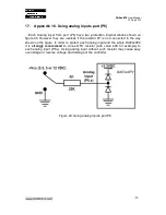
Страница 51: ...s if the resistor R1 is not connected in the way shown on the figure In order to protect each analog input and the whole DAEnetIP2 it is strongly recommend to connect R1 resistor with value 22K for example to each analog input P6 x Using analog input without such resistor may cause easy overvoltage or reverse voltage and damage of the controller Figure 40 Using analog inputs port P6 51 ...

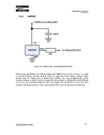
Страница 52: ...oltage during 25 С 3V As DAEnetIP2 ADC works in range of 0 3 3V actually with directly connected LM335 it is not possible to measure temperatures over 57 С Moreover the output of LM335Z can exceed 3 3V and damage the ADC channel The easiest solution is using simple resistor divisor 3 1 so the output voltage during 25 С to be 1V It is important the divisor resistance to be smaller because this impr...

Страница 53: ...s this sensor does not work as zener diode neither output divisor Also its initial error is better than LM335 The only disadvantage is the minimal voltage is 4VDC and this makes the connection to DAEnetIP2 more difficult it can not be connected directly with only single IDC connector to P6 The 27K resistor acts like protection of the analog input P6 X and it is strongly recommend 53 ...

Страница 54: ...3 18 3 MCP9700A Figure 43 DAEnetIP2 and MCP9700A This sensor MCP9700A works in range 2 3 5 5V and that allows to be supplied from 3 3V pin which is mapped to P6 jumper Generally its parameters are better than the LM335Z and LM35DZ 54 ...

Страница 55: ...DAEnetIP2 User Manual 12 Sep 2013 19 Appendix 12 Mechanical drawing Figure 44 Mechanical drawing 55 ...

Страница 56: ... 22 03 2012 First official document version for firmware version 4 084 11 02 2013 Update with the new features of DAEnetIP2 regarding firmware version 4 097 08 04 2013 Wiring diagram for LM335Z correction 12 09 2013 Added appendix Using analog inputs P6 56 ...

Отзывы: