DAEnetIP2
User Manual
12 Sep 2013
Setting low level the I/O lines while monitoring restart
If this option is enabled
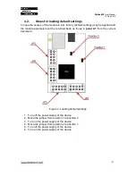
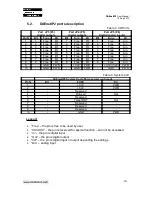
DAEnetIP2 will set in logical "0" all the outputs P3 and P5 (look figure 5 and table 3)
SNMP: Change its bit in cfgNewMode.0
Web: Menu „Setup-> Reset I/O ports on ping restart”
Incoming Ping request indicator "Ping LED"
Activating this mode will allow
DAEnetIP2 module to become in simple network analyzer (with set network
parameters), which can indicate "ping" requests to its IP address. Each received
request performs change of output "Ping LED" (see the i/o table description). The
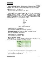
schematic bellow shows how to connect this pin to LED.
Figure 8. Connecting Ping LED
SNMP: Change its bit in cfgNewMode.0
Web: Menu „Setup-> Toggle JP6.4 on outgoing ping request”
Second
LED
indicator.
This indicator may show: „Power ON”, “Ping IN”,
“Ping OUT”, “Ping BOTH”, “DHCP valid IP”.
SNMP: Change its bit in cfgLED2mode.0
Web: Menu „Setup-> Second LED mode”
6.1.12. IO Ports settings
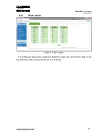
DAEnetIP2 has 8+8 digital I/O (P3/P5) and 8 analog inputs (P6). The analog
inputs may be used also for digital inputs (software conversion)
Figure 9. I/O ports
When Input is selected, that means this pin is input, otherwise it is output.
SNMP: Change its bit in cfgP3Dir.0, cfgP5Dir.0 (1=Out,2=In)
Web: Menu „Setup-> I/O ports settings”
-
15
-


