212385 Rev. A
www. s p e c s e l e c t . c o m
Page 4
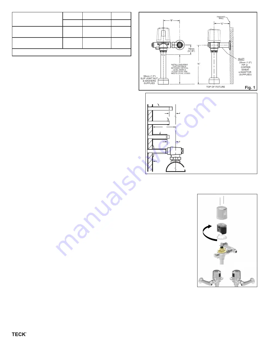
Product #
A
B
C
Max.
±11mm (
7
/
16
”)
Min.
All 81T201BT/
81T201HW variations*
292mm
(11½”)
121mm
(4¾”)
54mm
(2.13”)
All 81T231BT/
81T231HW variations*
330mm
(13”)
121mm
(4¾”)
54mm
(2.13”)
* Note: -30 models, B = 114mm - 131 mm (4.5” to 5.18”)
Flushometer MUST be paired with a fixture of equivalent flush
volume.
BEFORE THE FIRST FLUSH (COMPLETE VALVES)
FLUSH BOTH OLD AND NEW PIPES:
It is important to FLUSH and thoroughly CLEAN both new and old water
piping to ELIMINATE contaminants (eg. scale, sediment, gravel,
cuttings, solder, etc.) from the line.
Where the water has a sediment content, a PIPE STRAINER in the supply
line should alleviate that condition and protect working parts of flushometers
and faucets.
On a NEW INSTALLATION, always flush the valve 4 or 5 times to clean out
supply line debris. It is also advisable where more than one flushometer
is installed on a water line, to flush out the water piping through the last
flushometer outlet of the pipe line.
INSTALL FILTER SCREEN (included):
Note:
Place filter in stop bore with conical screen facing the water flow.
Caution:
Do not push filter in too far. Let filter seat against face of flush valve
tail. Periodic cleaning of the filter screen with water is recommended
depending on local water conditions to remove any dirt or sediment.
See filter screen M&I for additional installation information.
ELIMINATE AIR FROM VALVES:
The FIRST FLUSH should ELIMINATE all air from the TECK flushometer. DO
NOT ADJUST flushometer based on the results of the first flush.
TO PREVENT WATER HAMMER:
A water hammer arrestor may be installed at the last flushometer and/or at the back of an individual installation. This assures SMOOTHER
OPERATION of the valves and longer life for the working parts.
HANDS SHOULD BE CLEAN AND FREE OF GREASE AND OIL during any maintenance or handling of electronic housing components to
prevent possible damage to internal circuitry.
IF LEFT HAND STOP REQUIRED:
•
Remove the cover by taking out the two cover screws. See Figure 3.
Caution: DO NOT
remove the four screws (7b) that hold down the
cap/solenoid assembly
(6b).
•
You will now see the clear electronic compartment with a grey cover.
•
Now take hold of the compartment and very carefully, slowly lift the compartment about 1/4” and turn it
180°.
•
The sensor eye should now be on the other side.
•
Gently push the compartment back down, aligning the two screw holes on the clear case with the screw
holes on the brass solenoid cap/solenoid assembly (6b).
•
Rotate cover gasket (8a) 180° on brass cap.
•
Check for pinched wires between cover and clear case.
•
Ensure grey cover is snapped onto clear case and chrome button is properly seated.
•
Replace the cover and two cover screws - do not overtighten cover screws.
FLUSH VOLUME ADJUSTMENT:
3.4 U.S. gallons / 13.0 litres for water closets
1.6 U.S. gallons / 6.0 litres for water closets
1.27 U.S. gallons / 4.8 litres for water closets
0.5 U.S. gallon / 1.9 litres for urinal valves
0.125 U.S. gallon / 0.5 litre for urinal valves
The Regulating Screw (061024A, item #6a) may be adjusted, according to job conditions and fixture installed
to the proper water volume to flush that particular fixture (except -6, -48, -19 and -05 models which are not field adjustable).
NOTE:
4.8 and 6 Litre water closets or washdown urinals may require the Angle Stop to be set at only ONE TURN OPEN. For a SHORTER flush,
turn the Regulating Screw (061024A, item #6a) left (counter-clockwise) and right (clockwise) for a LONGER flush (except -6, -48, -19 and
-05 models which are not field adjustable).
RECOMMENDED WATER SUPPLY:
W/C - minimum flowing pressure: 25 psi (172 kPa), minimum flow rate: 25 gpm (95 lpm)
UR - minimum flowing pressure: 25 psi (172 kPa), minimum flow rate: 8 gpm (30 lpm)
"D"
25mm
(1")
38mm
(1½”)
Cover Tube
1" Copper Inlet Supply
Adapter
Finished
Wall
Of Fixture Spud
1" Copper Inlet Adapter Installation
1. Measure distance “D” from centre line
of fixture spud to finished wall.
2. Cut copper tube 1” shorter than
dimension “D”.
3. Push adapter onto copper tube until it
stops on the shoulder.
4. Solder adapter to copper tube.
5. Cut cover tube 1½” shorter than
dimension “D”.
6. Slide the wall flange and cover tube
over the supply pipe.
7. Thread the union stop onto the adapter,
and tighten set screw in flange.
Fig. 2
Fig. 3
Left Hand Stop
Right Hand Stop


