4
Η
Installation and Wiring
4-10
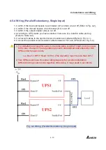
4-5-4 Wiring (Parallel Redundancy
, Single Input
)
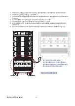
1. Confirm if the input and bypass input breaker (Q1 and Q2) are cut off (Refer to Fig. 4-2).
2. Confirm if the manual bypass circuit breaker (Q3) is cut off.
3. Confirm if the output breaker (Q4) is cut off.
4. According to UPS model you have selected, make use of a suitable cable and lug
(Refer to Table 4-3).
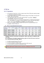
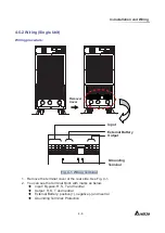
5. Connect all cables to the right terminal or location as indicated (Refer to Fig. 4-1).
6. Connect the parallel communication cable between UPS1 and UPS2 (Refer Fig. 4-4).
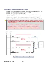
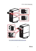
Fig. 4-4 Wiring (Parallel Redundancy, Single Input)
1. For installation of parallel system, the total cable length of input must be equal
to the one of output. This regulation prevents unbalanced load shared by two
UPSs under bypass mode.
i.e.: Res1 + OP1 = Res2 + OP2 = (The deviation must be less than 10%)
2. Two UPSs must have the same rating/capacity for parallel installation.
Different ratings cannot link together. Otherwise, it may result in accidents.
Содержание NH Plus Series
Страница 17: ...3 General View 3 2 3 1 1 Dimension Fig 3 1 Power Unit 80KVA 520 1 1165 5 910 1 Fig 3 2 Power Unit 120KVA...
Страница 18: ...Modulon NH Plus Series 3 3 Fig 3 3 External Battery Pack 26AH Fig 3 4 External Battery Pack 40AH...
Страница 55: ...6 Power Module Replacement 6 3 Fig 4 4 Wiring Parallel Redundancy Single Input Fail On Off Fail On Off...
Страница 87: ......
Страница 88: ......

