background image

Back to Contents Page


 Replacing the I/O Panel  

Dell Studio XPS™ 435T/9000 Service Manual 


1.

Follow the procedures in 

Before You Begin


2.

Remove the computer cover (see 

Replacing the Computer Cover

).  


3.

Remove the front panel (see 

Replacing the Front Panel

).  


4.

Remove the top cover (see 

Replacing the Top Cover

).  


5.

Disconnect the cables connected to the I/O panel from the system board.  


6.

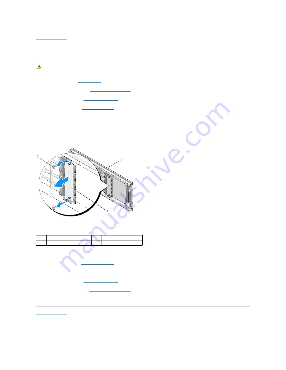
Remove the two screws that secure the I/O panel to the top cover.  


7.

Carefully remove the I/O panel from the computer.  


8.

To replace the I/O panel, replace the screws that secures the I/O panel to the top cover.  


9.

Replace the top cover (see 

Replacing the Top Cover

).  


10.

Replace the cables.  


11.

Replace the front panel (see 

Replacing the Front Panel

).  


12.

Replace the computer cover (see 

Replacing the Computer Cover

).  


13.

Connect your computer and devices to electrical outlets, and turn them on.  
 

Back to Contents Page


WARNING: 

Before working inside your computer, read the safety information that shipped with your computer. For additional safety best 

practices information, see the Regulatory Compliance Homepage at www.dell.com/regulatory_compliance. 

top cover 

I/O panel 

screws (2) 


Содержание Studio XPS 435 MT

Страница 1: ...ames may be used in this document to refer to either the entities claiming the marks and names or their products Dell Inc disclaims any proprietary interest in trademarks and trade names other than its own October 2008 Rev A00 Technical Overview Before You Begin Replacing the Computer Cover Replacing the Front Panel Replacing Memory Module s Replacing a PCI Express Card Replacing Drives Replacing ...

Страница 2: ...ign the holes in the badge back light to the projections on the front panel 6 Press the badge back light down until it clicks in place 7 Reconnect the badge back light cable 8 Replace the front panel see Replacing the Front Panel 9 Replace the computer cover see Replacing the Computer Cover Back to Contents Page WARNING Before working inside your computer read the safety information that shipped w...

Страница 3: ...down your operating system press and hold the power button for about 4 seconds to turn them off Safety Instructions Use the following safety guidelines to help protect your computer from potential damage and to help to ensure your own personal safety Before working inside your computer read the safety information that shipped with your computer For additional safety best practices information see ...

Страница 4: ... Back to Contents Page CAUTION To disconnect a network cable first unplug the cable from your computer and then unplug the cable from the network device CAUTION Before touching anything inside your computer ground yourself by touching an unpainted metal surface such as the metal at the back of the computer While you work periodically touch an unpainted metal surface to dissipate static electricity...

Страница 5: ...a secure place 6 If applicable disconnect any cables connected to the card 7 Press the securing tab grasp the card by its top corners and then ease it out of its connector 8 If you are replacing an existing card go to step 6 of Installing a PCI Express Card WARNING Before working inside your computer read the safety information that shipped with your computer For additional safety best practices i...

Страница 6: ... that came with the card for information on configuring customizing and making internal connections on the card 7 Align the card with the connector 8 Place the card in the connector and press down firmly Ensure that the card is fully seated in the slot 9 Replace the card retention bracket see Replacing the Card Retention Bracket 10 Connect any cables that should be attached to the card See the doc...

Страница 7: ... on installing drivers and software for your card see the documentation that shipped with the card Installed Removed Sound Card 1 Enter system setup see System Setup 2 Go to Advanced Chipset Features and select Onboard Audio Controller and then change the setting to Disabled 3 Connect the external audio devices to the sound card s connectors 1 Enter system setup see System Setup 2 Go to Advanced C...

Страница 8: ...up see System Setup and restore the settings you recorded in step 1 Back to Contents Page WARNING Before working inside your computer read the safety information that shipped with your computer For additional safety best practices information see the Regulatory Compliance Homepage at www dell com regulatory_compliance WARNING A new battery can explode if it is incorrectly installed Replace the bat...

Страница 9: ...over perform the removal procedure in reverse order Back to Contents Page WARNING Before working inside your computer read the safety information that shipped with your computer For additional safety best practices information see the Regulatory Compliance Homepage at www dell com regulatory_compliance WARNING To guard against likelihood of electric shock laceration by moving fan blades or other u...

Страница 10: ...essor WARNING Before working inside your computer read the safety information that shipped with your computer For additional safety best practices information see the Regulatory Compliance Homepage at www dell com regulatory_compliance CAUTION Do not perform the following steps unless you are familiar with hardware removal and replacement Performing these steps incorrectly could damage your system...

Страница 11: ...see Replacing the Computer Cover 20 Connect your computer and devices to electrical outlets and then turn them on 1 processor cover 2 tab 3 alignment notch 2 4 processor 5 socket 6 center cover latch 7 release lever 8 processor pin 1 indicator CAUTION You must position the processor correctly in the socket to avoid permanent damage to the processor and the computer when you turn on the computer CA...

Страница 12: ...Back to Contents Page ...

Страница 13: ...WARNING Before working inside your computer read the safety information that shipped with your computer For additional safety best practices information see the Regulatory Compliance Homepage at www dell com regulatory_compliance NOTE The system board does not support IDE devices NOTE The 3 5 inch FlexDock is not interchangeable with the hard drive carrier CAUTION If you are replacing a hard drive...

Страница 14: ... screws securing the optical drive to the chassis 6 Push and slide the optical drive out through the front of the computer 7 If you are not replacing the drive a Replace the drive panel insert see Replacing the Drive Panel Insert b Go to step 12 8 If you are replacing the optical drive or installing a new one slide the drive into place 9 Align the screw holes in the optical drive with the screw ho...

Страница 15: ...FlexDock a Remove the drive panel insert if applicable see Replacing the Drive Panel Insert b Remove the FlexDock break away metal plate if applicable see Removing the FlexDock Break Away Metal Plate c Remove the FlexDock from its packaging 9 Gently slide the FlexDock into place in the FlexDock slot 10 Align the screw holes on the FlexDock with the screw holes on the FlexDock slot 11 Replace the t...

Страница 16: ...press on the insert lever inward to release the lock 3 Pull the FlexDock drive insert away from the front panel 4 To replace the FlexDock drive insert align the FlexDock drive insert in place 5 Push the insert lever towards the front panel till it snaps into place Replacing the Drive Panel Insert Align the drive panel insert along the edges of the empty slot of the FlexDock or an optical drive and...

Страница 17: ...ge CAUTION To comply with FCC regulations it is recommended that you replace the drive panel insert whenever the FlexDock or optical drive is removed from the computer 1 back of the computer 2 drive panel insert optional ...

Страница 18: ... Cover Replacing the Processor Fan and Heat Sink Assembly 1 Follow the procedures in Before You Begin 2 Remove the computer cover see Replacing the Computer Cover 3 Disconnect the processor fan cable from the CPU_FAN connector on the system board see System Board Components WARNING Before working inside your computer read the safety information that shipped with your computer For additional safety...

Страница 19: ...ter cover see Replacing the Computer Cover 13 Connect your computer and devices to electrical outlets and turn them on Back to Contents Page CAUTION To ensure maximum cooling for the processor do not touch the heat transfer areas on the processor heat sink The oils in your skin can reduce the heat transfer capability of the thermal pads CAUTION When you remove the processor fan and heat sink assem...

Страница 20: ...insert 5 To replace the front panel align and insert the front panel clamps into the clamp insert 6 Rotate the front panel towards the computer until it snaps into place on the front of the computer 7 Replace the computer cover see Replacing the Computer Cover Back to Contents Page WARNING Before working inside your computer read the safety information that shipped with your computer For additiona...

Страница 21: ...el to the chassis 10 Connect the cables to the system board 11 Replace any expansion cards if necessary see Replacing a PCI Express Card 12 Replace the front panel see Replacing the Front Panel 13 Replace the computer cover see Replacing the Computer Cover 14 Connect your computer and devices to electrical outlets and turn them on Back to Contents Page WARNING Before working inside your computer r...

Страница 22: ......

Страница 23: ...itional safety best practices information see the Regulatory Compliance Homepage at www dell com regulatory_compliance 1 securing clip 2 memory module connector CAUTION Do not install ECC memory modules CAUTION If you remove your original memory modules from the computer during a memory upgrade keep them separate from any new modules that you may have even if you purchased the new modules from Del...

Страница 24: ...pears stating that memory size has changed press F1 to continue 12 Log on to your computer 13 Right click the My Computer icon on your Microsoft Windows desktop and click Properties 14 Click the General tab 15 To verify that the memory is installed correctly check the amount of memory RAM listed Back to Contents Page 1 cutouts 2 2 memory module 3 notch 4 tab on the memory module connector CAUTION ...

Страница 25: ...Regulatory Compliance Homepage at www dell com regulatory_compliance WARNING To guard against likelihood of electric shock laceration by moving fan blades or other unexpected injuries always unplug your computer from the electrical outlet before removing the cover CAUTION Do not perform the following steps unless you are familiar with hardware removal and replacement Performing these steps incorre...

Страница 26: ...Back to Contents Page ...

Страница 27: ... the rubber foot to secure the rubber foot to the chassis Back to Contents Page WARNING Before working inside your computer read the safety information that shipped with your computer For additional safety best practices information see the Regulatory Compliance Homepage at www dell com regulatory_compliance WARNING To guard against likelihood of electric shock laceration by moving fan blades or o...

Страница 28: ...ety best practices information see the Regulatory Compliance Homepage at www dell com regulatory_compliance CAUTION Do not perform the following steps unless you are familiar with hardware removal and replacement Performing these steps incorrectly could damage your system board For technical assistance see the Setup Guide WARNING Despite having a plastic shield the processor fan and heat sink asse...

Страница 29: ... Processor 14 Replace any expansion cards on the system board see Installing a PCI Express Card 15 Replace the computer cover see Replacing the Computer Cover 16 Connect your computer and devices to electrical outlets and turn them on 17 Flash the system BIOS as needed Back to Contents Page CAUTION Ensure that the heat sink assembly is correctly seated and secure NOTE For information on flashing t...

Страница 30: ... again Menu Appears on top of the System Setup window This field provides a menu to access to the System Setup options Press the and keys to navigate As a Menu option is highlighted the Options List lists the options that define the hardware installed on you computer Options List Appears on the left side of the System Setup window The field lists features that define the configuration of your comp...

Страница 31: ...roller Enabled or Disabled Enabled by default Onboard LAN Boot ROM Enabled or Disabled Disabled by default 1394 Controller Enabled or Disabled Enabled by default Boot Device Configuration Boot Settings Configuration Configures the settings during system boot Hard Disk Boot Priority Sets the hard drive boot priority The items displayed are dynamically updated according to the hard drives detected F...

Страница 32: ...ain The Boot Device Menu appears listing all available boot devices Each device has a number next to it 4 On the Boot Device Menu choose the device you want to boot from For example if you are booting to a USB memory key highlight USB Flash Device and press Enter Changing Boot Sequence for Future Boots 1 Enter system setup see Entering System Setup 2 Use the arrow keys to highlight the Boot Device...

Страница 33: ... Replace the computer cover see Replacing the Computer Cover 8 Connect your computer and devices to electrical outlets and turn them on Clearing CMOS Settings 1 Follow the procedures in Before You Begin 2 Remove the computer cover see Replacing the Computer Cover 3 Locate the 3 pin CMOS connector CLR_CMOS on the system board see System Board Components WARNING The computer must be disconnected fro...

Страница 34: ...lick Download Now to download the file 4 If the Export Compliance Disclaimer window appears click Yes I Accept this Agreement The File Download window appears 5 Click Save this program to disk and then click OK The Save In window appears 6 Click the down arrow to view the Save In menu select Desktop and then click Save The file downloads to your desktop 7 Click Close when the Download Complete win...

Страница 35: ...mputer read the safety information that shipped with your computer For additional safety best practices information see the Regulatory Compliance Homepage at www dell com regulatory_compliance 1 hard drive 2 FlexDock 3 power supply 4 optical drive 1 processor socket CPU 2 processor fan connector CPU_FAN 3 memory module connector DIMM_4 4 memory module connector DIMM_1 5 memory module connector 6 m...

Страница 36: ...ont panel connector FP1 16 Card reader USB connector F_USB1 17 front USB connector F_USB2 18 front USB connector F_USB3 19 FlexDock USB connector F_USB4 20 CMOS jumper CLR_CMOS 21 front 1394 connector F_1394 22 S PDIF out connector SPDIF_OUT2 23 front audio connector F_AUDIO 24 PCI Express x1 connector PCI EX1_2 25 PCI Express x16 connector PCI EX16_1 26 battery socket BAT 27 PCI Express x1 connec...

Страница 37: ...ta start button logo are either trademarks or registered trademarks of Microsoft Corporation in the United States and or other countries Other trademarks and trade names may be used in this document to refer to either the entities claiming the marks and names or their products Dell Inc disclaims any proprietary interest in trademarks and trade names other than its own March 2009 Rev A00 Back to Co...

Страница 38: ...o the computer 5 Disconnect the cables from the top I O panel 6 Pull the release tab with one hand and slide the top cover away from the chassis 7 Disconnect the power LED cable from the top cover WARNING Before working inside your computer read the safety information that shipped with your computer For additional safety best practices information see the Regulatory Compliance Homepage at ww dell ...

Страница 39: ... Remove the I O panel see Replacing the I O Panel 9 Set the computer top cover aside in a secure location 10 To replace the top cover perform the removal procedure in reverse order Back to Contents Page ...

Страница 40: ...nel from the computer 8 To replace the I O panel replace the screws that secures the I O panel to the top cover 9 Replace the top cover see Replacing the Top Cover 10 Replace the cables 11 Replace the front panel see Replacing the Front Panel 12 Replace the computer cover see Replacing the Computer Cover 13 Connect your computer and devices to electrical outlets and turn them on Back to Contents P...

Отзывы: