


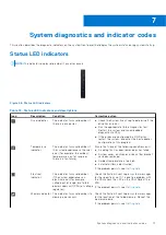


Table 72. Status LED indicators and descriptions (continued)
Icon
Description
Condition
Corrective action
PCIe indicator
The indicator turns solid amber if a
PCIe card experiences an error.
Restart the system. Update any required drivers for
the PCIe card. Reinstall the card.
If the problem persists, see
.
NOTE:
For more information about the
supported PCIe cards, see the Expansion card
installation guidelines section.
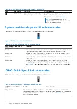
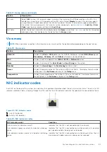
System health and system ID indicator codes
The system health and system ID indicator is located on the left control panel of the system.
Figure 67. System health and system ID indicator
Table 73. System health and system ID indicator codes
System health and system ID
indicator code
Condition
Solid blue
Indicates that the system is powered on, is healthy, and system ID mode is not active.
Press the system health and system ID button to switch to system ID mode.
Blinking blue
Indicates that the system ID mode is active. Press the system health and system ID
button to switch to system health mode.
Solid amber
Indicates that the system is in fail-safe mode. If the problem persists, see the
section.
Blinking amber
Indicates that the system is experiencing a fault. Check the System Event Log
for specific error messages. For information about the event and error messages
generated by the system firmware and agents that monitor system components, go
to
>
Look Up
>
Error Code
, type the error code, and then click
Look it
up
.
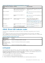
iDRAC Quick Sync 2 indicator codes
iDRAC Quick Sync 2 module (optional) is located on the left control panel of the system.
Table 74. iDRAC Quick Sync 2 indicators and descriptions
iDRAC Quick Sync 2 indicator
code
Condition
Corrective action
Off (default state)
Indicates that the iDRAC Quick Sync 2
feature is powered off. Press the iDRAC
Quick Sync 2 button to power on the
iDRAC Quick Sync 2 feature.
If the LED fails to power on, reseat the left
control panel flex cable and check. If the problem
persists, see the
78
System diagnostics and indicator codes
Содержание PowerFlex R750
Страница 1: ...Dell Technologies PowerFlex Custom Node R750 Owner s Guide October 2021 Rev 01 ...
Страница 14: ...Figure 9 Service information Figure 10 Memory information and system board connectors 14 System overview ...
Страница 16: ...Figure 15 System tasks Figure 16 Heat sink Figure 17 BOSS S2 Figure 18 Express service tag 16 System overview ...


