


Cable routing
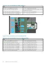
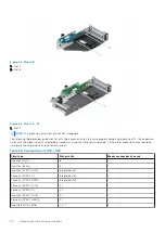
Figure 40. Control panels and intrusion switch
Table 30. Control panels, BOSS S2 and VGA cabling
From
To
Left control panel connector
Left control panel (LCP)
Right control panel connector
Right control panel (RCP)
Front VGA connector
VGA on RCP
BOSS_CARD_PWR (BOSS S2 module power connector on
system board)
BOSS_PWR (BOSS S2 module power connector on BOSS S2
module)
SL6_PCH_PA4 (BOSS signal connector on system board)
BOSS signal on BOSS S2 card module
38
Component installation guidelines
Содержание PowerFlex R750
Страница 1: ...Dell Technologies PowerFlex Custom Node R750 Owner s Guide October 2021 Rev 01 ...
Страница 14: ...Figure 9 Service information Figure 10 Memory information and system board connectors 14 System overview ...
Страница 16: ...Figure 15 System tasks Figure 16 Heat sink Figure 17 BOSS S2 Figure 18 Express service tag 16 System overview ...


