


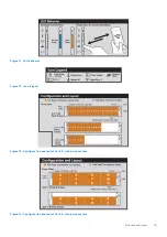


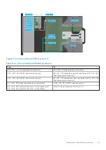


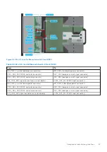

Figure 21. 16 x 2.5-inch NVMe with fPERC and Riser 1C
Table 11. 16 x 2.5-inch NVMe with fPERC and Riser 1C
From
To
SIG_PWR_1 (system board power connector)
BP_PWR_1 (backplane power connector)
CTRL_SRC_PA1 (fPERC controller connector)
BP_DST_PA1 (backplane signal connector) and BP_DST_PB1
(backplane signal connector)
CTRL_SRC_PB1 (fPERC controller connector)
BP_DST_PA2 (backplane signal connector) and BP_DST_PB2
(backplane signal connector)
SL1_CPU2_PB1 (signal connector on system board)
CTRL_DST_PA1 (fPERC input connector)
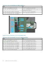
SIG_PWR_2 (system board power connector)
BP_PWR_1 (backplane power connector)
CTRL_SRC_PA1 (fPERC controller connector)
BP_DST_PA1 (backplane signal connector) and BP_DST_PB1
(backplane signal connector)
CTRL_SRC_PB1 (fPERC controller connector)
BP_DST_PA2 (backplane signal connector) and BP_DST_PB2
(backplane signal connector)
SL2_CPU2_PA1 (signal connector on system board)
CTRL_DST_PA1 (fPERC input connector)
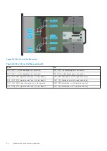
SL3_CPU1_PB2 (signal connector on system board) and
SL4_CPU1_PA2 (signal connector on system board)
Riser 1C (signal connector from Riser 1C)
22
Component installation guidelines
Содержание PowerFlex R750
Страница 1: ...Dell Technologies PowerFlex Custom Node R750 Owner s Guide October 2021 Rev 01 ...
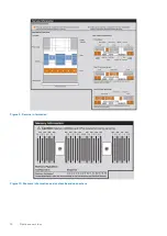
Страница 14: ...Figure 9 Service information Figure 10 Memory information and system board connectors 14 System overview ...
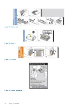
Страница 16: ...Figure 15 System tasks Figure 16 Heat sink Figure 17 BOSS S2 Figure 18 Express service tag 16 System overview ...


