

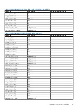


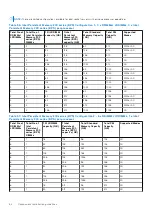


Table 61. Intel Persistent Memory 200 series (BPS) Configuration 6 - 12 x RDIMMs/ LRDIMMs, 2 x Intel
Persistent Memory 200 series (BPS) per processor
Total No of
RDIMMs /
LRDIMMs
Total No of
Intel
Persistent
Memory 200
series (BPS)
DIMMs
1 R/LRDIMM
capacity (GB)
1 Intel
Persistent
Memory 200
series (BPS)
capacity (GB)
Total Standard
Memory Capacity
(GB)
Total PM
Capacity
(GB)
Supported Modes
12
2
16
128
192
256
AD
12
2
32
128
384
256
AD
12
2
64
128
768
256
AD
12
2
128
128
1536
256
AD
12
2
256
128
3072
256
AD
12
2
16
256
192
512
AD
12
2
32
256
384
512
AD
12
2
64
256
768
512
AD
12
2
128
256
1536
512
AD
12
2
256
256
3072
512
AD
12
2
16
512
192
1024
AD
12
2
32
512
384
1024
AD
12
2
64
512
768
1024
AD
12
2
128
512
1536
1024
AD
12
2
256
512
3072
1024
AD
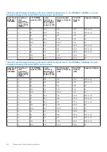
NVDIMM-N memory module installation guidelines
The following are the recommended guidelines for installing NVDIMM-N memory modules:
●
Each system supports memory configurations with 1, 2, or 4 NVDIMM-Ns per processor.
●
Supported configurations have dual processors and a minimum of 8x RDIMMs.
●
Maximum of 8 NVDIMM-Ns can be installed in a system.
●
NVDIMM-Ns or RDIMMs must not be mixed with LRDIMMs.
●
DDR4 NVDIMM-Ns must be populated only on the black release tabs on processor 1 and 2.
●
General memory guideline rules are also applicable.
●
All RDIMMs are to populated on slots 0 and all NVDIMMs are populated on slots 1.
NOTE:
NVDIMM-N memory slots are not hot-pluggable.
For more information about the supported NVDIMM-N configurations, see the
NVDIMM-N User Guide
Table 62. Supported NVDIMM-N for dual processor configurations
Configuration
Description
Memory population rules
RDIMMs
NVDIMM-N
Configuration 1
8x (16 GB/32 GB/64 GB)
4x NVDIMM-N
Processor1 {A1, 2, 3, 4}
Processor2 {B1, 2, 3, 4}
Processor1 {A5, 6}
Processor2 {B5, 6}
Configuration 2
8x (16 GB/32 GB/64 GB)
8x NVDIMM-N
Processor1 {A1, 2, 3, 4}
Processor2 {B1, 2, 3, 4}
Processor1 {A5, 6, 7, 8}
Processor2 {B5, 6, 7, 8}
Component installation guidelines
67
Содержание PowerFlex R750
Страница 1: ...Dell Technologies PowerFlex Custom Node R750 Owner s Guide October 2021 Rev 01 ...
Страница 14: ...Figure 9 Service information Figure 10 Memory information and system board connectors 14 System overview ...
Страница 16: ...Figure 15 System tasks Figure 16 Heat sink Figure 17 BOSS S2 Figure 18 Express service tag 16 System overview ...


