NOTE:
This step applies only to computers shipped with a power button with fingerprint reader installed.
5. Connect the following cables to the respective connectors on the system board:
a. Touch-screen cable, if applicable
NOTE:
This step applies only to computers shipped with a touch screen installed.
b. Display cable
c. IR-camera cable, if applicable
NOTE:
This step applies only to computers shipped with an IR camera installed.
d. Sensor daughter-board cable, if applicable
NOTE:
This step applies only to computers shipped with a sensor daughter-board installed.
e. Main-speakers daughter-board FPC
f. Tweeter speaker cable
g. Audio daughter-board FFC
h. Touchpad FFC
i.
USH daughter-board FFC, if applicable
NOTE:
This step applies only to computers shipped with a USH daughter-board installed.
j.
LED daughter-board FFC
6. Adhere the tape to secure the display cable to the system board.
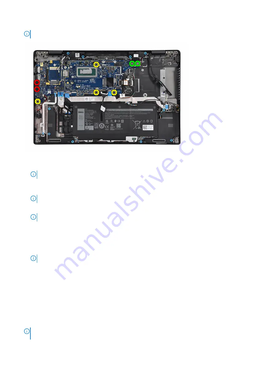
7. Align and place the display-cable bracket into its slot on the system board.
8. Replace the two screws (M2x2) to secure the display-cable bracket to the system board.
9. Route the WLAN-antenna cables through the routing guides and connect them to the respective connectors on the system
board.
10. Align and place the WLAN bracket into its slot on the system board.
11. Replace the screw (M2x2) to secure the WLAN bracket to the system board.
12. Route the #1 Darwin antenna cable, #2 Darwin antenna cable, #6 black/gray WWAN Aux1 antenna cable and #5 white/gray
WWAN Main antenna cable through the respective routing guides on the palm-rest and keyboard assembly.
NOTE:
When routing the WWAN-antenna cables, secure the Darwin cables and black/gray WWAN-antenna cable (for
WWAN configuration) in place with the sponges.
72
Removing and installing components
Содержание P110F
Страница 1: ...Latitude 7530 Service Manual Regulatory Model P110F Regulatory Type P110F002 April 2022 Rev A00 ...
Страница 18: ...18 Removing and installing components ...
Страница 36: ...36 Removing and installing components ...
Страница 46: ...46 Removing and installing components ...
Страница 61: ...Removing and installing components 61 ...
Страница 70: ...70 Removing and installing components ...
Страница 82: ...82 Removing and installing components ...
Страница 104: ...To clear the alert set the Clear Intrusion Warning to ON in the Security menu of the BIOS setup 104 BIOS setup ...


