background image

Installing Drives

7-5

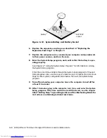
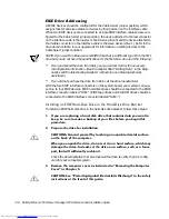
Most interface connectors are keyed for correct insertion; that is, a notch or a missing 
pin on one connector matches a tab or a filled-in hole on the other connector (see Fig-
ure 7-5). Keying ensures that the pin-1 wire in the cable (indicated by the colored strip 
along one edge of the cable) goes to the pin-1 end of the connector.

The pin-1 end of a connector on a board or a card is usually indicated by a silk-
screened “1” printed directly on the board or card.

&$87,21:KHQFRQQHFWLQJDQLQWHUIDFHFDEOHGRQRWUHYHUVHWKHLQWHUIDFH

FDEOHGRQRWSODFHWKHFRORUHGVWULSDZD\IURPSLQRIWKHFRQQHFWRU

5HYHUVLQJWKHFDEOHSUHYHQWVWKHGULYHIURPRSHUDWLQJDQGFRXOGGDPDJH

WKHFRQWUROOHUWKHGULYHRUERWK

,QVWDOOLQJD'ULYHLQD,QFK'ULYH%D\

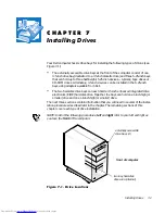
The 5.25-inch drive bays can accommodate any of the following types of half-height 
drives:

‡

A diskette drive or tape drive that uses the diskette/tape drive interface on the 
system board

‡

A CD-ROM or tape drive that uses the secondary EIDE interface on the system 
board

‡

A CD-ROM or tape drive that uses its own controller card

To install a drive in a 5.25-inch drive bay, follow these steps:

 8QSDFNWKHGULYHDQGSUHSDUHLWIRULQVWDOODWLRQ

&$87,216*URXQG\RXUVHOIE\WRXFKLQJDQXQSDLQWHGPHWDOVXUIDFH

RQWKHEDFNRIWKHFRPSXWHU

:KHQ\RXXQSDFNWKHGULYHGRQRWVHWLWRQDKDUGVXUIDFHZKLFKPD\

GDPDJHWKHGULYH,QVWHDGVHWWKHGULYHRQDVXUIDFHVXFKDVDIRDP

SDGWKDWZLOOVXIILFLHQWO\FXVKLRQLW

Check the documentation that accompanied the drive to verify that the drive is 
configured for your computer system. Change any settings necessary for your 
configuration.

NOTE: If you are installing a non-EIDE tape drive, check the documentation for 
the drive to determine the jumper or switch settings used to designate the drive 
as drive address DS4 (not DS2 or DS3 as may be indicated in the drive documen-
tation). Unless the drive is already set to drive 4, reconfigure its jumper or switch 
setting (see “Jumpers” and “Switches” in Chapter 5).

If you are installing an EIDE CD-ROM or EIDE tape drive, configure the drive for 
the Cable Select setting.

Содержание OptiPlex G1

Страница 1: ... ZZZ GHOO FRP HOO 2SWL3OH 0LQL 7RZHU 0DQDJHG 3 6 VWHPV 5 5 1 1 167 7 21 8 ...

Страница 2: ...trademarks and Windows for Workgroups is a trademark of Microsoft Corporation IBM and OS 2 are registered trademarks of International Business Machines Corporation 3Com and EtherLink are registered trademarks and Fast EtherLink is a trademark of 3Com Corporation VESA is a registered trademark of Video Electronics Standards Association UNIX is a registered trademark of UNIX System Laboratories Inc ...

Страница 3: ...vailable in your location Before working inside the computer unplug the system to help prevent electric shock or system board damage Certain system board components continue to receive power any time the computer is connected to AC power To help avoid possible damage to the system board wait 5 seconds after turning off the system before disconnecting a device from the computer To help prevent elec...

Страница 4: ...tance usually 510 to 610 millimeters 20 to 24 inches from your eyes Make sure the monitor screen is at eye level or slightly lower when you are sitting in front of the monitor Adjust the tilt of the monitor its contrast and brightness settings and the lighting around you such as overhead lights desk lamps and the curtains or blinds on nearby windows to minimize reflections and glare on the monitor...

Страница 5: ...HP ERDUG ZDLW VHFRQGV DIWHU WXUQLQJ RII WKH V VWHP EHIRUH UHPRYLQJ D FRPSRQHQW IURP WKH V VWHP ERDUG RU GLVFRQQHFWLQJ D SHULSKHUDO GHYLFH IURP WKH FRPSXWHU 7XUQ RII RXU FRPSXWHU DQG DQ SHULSKHUDOV LVFRQQHFW RXU FRPSXWHU DQG SHULSKHUDOV IURP WKHLU SRZHU VRXUFHV OVR GLVFRQQHFW DQ WHOHSKRQH RU WHOHFRPPXQLFDWLRQ OLQHV IURP WKH FRPSXWHU Doing so reduces the potential for personal injury or shock monito...

Страница 6: ... LVFKDUJH Static electricity can harm delicate components inside your computer To prevent static damage discharge static electricity from your body before you touch any of your computer s electronic components such as the microprocessor You can do so by touching an unpainted metal surface on the computer chassis As you continue to work inside the computer periodically touch an unpainted metal surf...

Страница 7: ...ix The following caution may appear throughout this document to remind you of these precautions 87 21 6HH 3URWHFWLQJ JDLQVW OHFWURVWDWLF LVFKDUJHµ LQ WKH VDIHW LQVWUXFWLRQV DW WKH IURQW RI WKLV JXLGH ...

Страница 8: ...x ...

Страница 9: ...he default configuration of the system s integrated video and audio controllers or who want to connect their system to a network should read Chapter 4 Using Integrated Devices This chapter describes the configuration software provided for the integrated video and audio controllers and provides information on connecting the system to a network configuring the net work interface controller NIC and i...

Страница 10: ...puter s back panel The Diagnostics and Troubleshooting Guide includes troubleshooting procedures and instructions for using the Dell Diagnostics to test your computer system You may also have one or more of the following documents NOTE Documentation updates are sometimes included with your system to describe changes to your system or software Always read these updates before consulting any other d...

Страница 11: ...he labeling that appears on the keys on a keyboard are enclosed in angle brackets Example Enter Key combinations are series of keys to be pressed simultaneously unless other wise indicated to perform a single function Example Ctrl Alt Enter Commands presented in lowercase bold are for reference purposes only and are not intended to be typed when referenced Example Use the format command to In cont...

Страница 12: ... can be a system message for example or it can be text that you are instructed to type as part of a command referred to as a command line Screen text is presented in the Courier New font Example The following message appears on your screen 1R ERRW GHYLFH DYDLODEOH Example Type PG F SURJUDPV and press Enter Variables are placeholders for which you substitute a value They are presented in italics Ex...

Страница 13: ...ock Ring 1 8 Passwords 1 9 Using the Power Switch 1 9 Energy Star Compliance 1 10 Important Note for Windows 95 Users 1 10 Intel PIIX4e INF Update Installer for Windows 95 1 11 Accessing Online Documentation 1 12 Getting Help 1 13 KDSWHU 8VLQJ WKH 6 VWHP 6HWXS 3URJUDP Entering the System Setup Program 2 1 System Setup Screen 2 2 Using the System Setup Program 2 2 System Setup Categories 2 4 System...

Страница 14: ...arallel Port Mode 2 10 IDE Drive Interface 2 10 Diskette Interface 2 11 PC Speaker 2 11 Video DAC Snoop 2 11 System Security 2 11 System Password 2 11 Password Status 2 12 Setup Password 2 12 Chassis Intrusion 2 12 Keyboard NumLock 2 13 Report Keyboard Errors 2 13 Auto Power On 2 13 Wakeup On LAN 2 13 Power Management 2 13 Saving Monitor Power 2 14 Saving EIDE Hard Disk Drive Power 2 14 Asset Tag ...

Страница 15: ...te 3 4 Starting the ICU 3 5 Accessing Help 3 5 Making Selections in the ICU 3 5 Adding a Listed Card 3 6 Adding an Unlisted Card 3 9 Modifying a Card 3 11 Removing a Card 3 13 Viewing Resources 3 13 Saving the System Configuration 3 14 Exiting From the ICU 3 14 Locking and Unlocking Cards 3 15 Locking and Unlocking All Resources 3 15 Locking and Unlocking Configuration Resources 3 16 KDSWHU 8VLQJ ...

Страница 16: ...RQV Expansion Cards 6 2 Expansion Slots 6 3 Installing an Expansion Card 6 4 Removing an Expansion Card 6 6 Adding Memory 6 7 Performing a Memory Upgrade 6 8 Installing a DIMM 6 10 Removing a DIMM 6 10 Adding Video Memory 6 11 Upgrading the Microprocessor 6 12 Replacing the System Battery 6 16 KDSWHU QVWDOOLQJ ULYHV Removing and Replacing the Front Bezel 7 2 Removing and Replacing Front Panel Inse...

Страница 17: ...JLBDKJ C 6 1P PTUB F JOTUSVLDKF CF QJFD FËTUXB C 6 NOM 024 Information Mexico Only C 7 Información para NOM 024 únicamente para México C 8 BCIQ Notice for Taiwan Only C 8 SSHQGL DUUDQWLHV DQG 5HWXUQ 3ROLF Limited Three Year Warranty U S and Canada Only D 1 Coverage During Year One D 1 Coverage During Years Two and Three D 2 General D 2 Total Satisfaction Return Policy U S and Canada Only D 3 QGH L...

Страница 18: ...atures 6 2 Figure 6 2 Expansion Cards 6 3 Figure 6 3 Riser Board Expansion Card Connectors 6 4 Figure 6 4 Removing the Filler Bracket 6 5 Figure 6 5 Installing an Expansion Card 6 5 Figure 6 6 DIMMs and DIMM Sockets 6 8 Figure 6 7 Installing a DIMM 6 10 Figure 6 8 Removing a DIMM 6 11 Figure 6 9 Installing a Video Memory Upgrade Module 6 12 Figure 6 10 Disconnecting the Microprocessor 6 14 Figure ...

Страница 19: ...ry Requirements 1 3 Table 2 1 System Setup Navigation Keys 2 3 Table 2 2 Power Time Out Periods 2 15 Table 3 1 ICU Keys 3 6 Table 5 1 System Board Jumper Settings 5 10 Table 5 2 System Board and Riser Board Connectors and Sockets 5 11 Table 6 1 Sample DIMM Configuration Options 6 8 Table A 1 Technical Specifications A 1 Table B 1 Configuration Utility Messages B 1 Table B 2 Configuration Manager M...

Страница 20: ...xxii ...

Страница 21: ...that runs at one of the following speeds An internal speed of 266 300 or 333 MHz and an external bus speed of 66 MHz An internal speed of 350 400 or 450 MHz and an external bus speed of 100 MHz The Intel Pentium II microprocessor includes MMX technology designed to han dle complex multimedia and communications software This microprocessor incorporates new instructions and data types as well as a t...

Страница 22: ...ICU allows you to configure existing non Plug and Play ISA expansion cards for conflict free operation Also because the system BIOS is stored in flash memory it can be updated to support future enhancements to the Plug and Play standard Wakeup On LAN capability which when enabled in the System Setup program allows the system to be powered up from a server management console Wakeup On LAN capabilit...

Страница 23: ...hanced integrated drive electronics EIDE support The primary and secondary interface are both located on the PCI bus to provide faster data throughput Each interface supports high capacity EIDE drives as well as devices such as advanced technology attachment ATA 33 hard disk drives EIDE CD ROM drives and EIDE tape drives Two high performance serial ports and one bidirectional parallel port for con...

Страница 24: ...ice tag number available through the System Setup program In addition a customer definable asset tag number can be assigned via a software support utility and viewed on the System Setup screens For more information see your online System User s Guide and Chapter 2 Using the Sys tem Setup Program of this document Advanced power management options that can reduce the energy consumption of your syste...

Страница 25: ...ces sories folder The Dell OpenManage program which is a DMI browser that allows you to view your computer s current hardware configuration and operating system ver sion The Dell OpenManage provides information you may need if you call Dell for technical assistance or if you install hardware or software in your system The Dell OpenManage program is located in the Dell Accessories folder For more i...

Страница 26: ...g manage ability features which are based on the DMI 2 0 specification DXOW 0DQDJHPHQW Fault Management features of the Dell OpenManage include Alerts to warn you about events generated by SMART drives on a local or remote system and about thermal errors An event log that stores events in a text file and reports information about the event under the following categories System Name Component Name ...

Страница 27: ...k administrators to remotely view enter and modify an asset tag for a remote system in a Dell DMI network Automated and manual mapping of one or more groups to a user defined directory 6HFXULW 0DQDJHPHQW Security Management features of the Dell OpenManage include Password security that enables network administrators to maintain standard attribute values for the local and remote systems in a Dell D...

Страница 28: ...set Auto Power On to turn on the system either every day or every Monday through Friday NOTE This feature does not work if the system is shut off using a power strip or surge protector 6HFXULW HDWXUHV Your Dell OptiPlex G1 system has the following integrated security features KDVVLV QWUXVLRQ A built in chassis intrusion alarm displays the status of the system chassis intrusion monitor If the chass...

Страница 29: ...trict access to the system Additional protection is available through the System Setup program When the Setup Password category is set to Enabled Password Status allows you to prevent the system password from being changed or disabled at boot time For more information see Chapter 2 Using the System Setup Program 8VLQJ WKH 3RZHU 6ZLWFK If the system does not turn off when the power switch is presse...

Страница 30: ... power consumption beyond the limits set by the EPA s Energy Star Computers program LJXUH QHUJ 6WDU PEOHP The EPA s Energy Star Computers program is a joint effort between the EPA and com puter manufacturers to reduce air pollution by promoting energy efficient computer products The EPA estimates that use of Energy Star computer products can save computer users up to two billion dollars annually i...

Страница 31: ...own load Windows 95 from a server to client systems make sure that you have the Windows 95 backup media for the OptiPlex G1 system on your server before downloading QWHO 3 H 1 8SGDWH QVWDOOHU IRU LQGRZV NOTE The following procedure applies only to versions of Windows 95 installed by Dell If you must reinstall Windows 95 on your computer system you also need to run the Intel PIIX4e INF Update Insta...

Страница 32: ... dialog box appears and informs you that the system configuration settings have changed and asks if you want to restart your system OLFN 2 WR UHVWDUW WKH V VWHP FFHVVLQJ 2QOLQH RFXPHQWDWLRQ The online System User s Guide installed on your hard disk drive contains information on the following topics Using the online System User s Guide System features Using drivers and utilities Using the System Se...

Страница 33: ...on t understand a procedure described in this guide or if your system does not perform as expected For informa tion on these help tools see the chapter titled Getting Help in your Diagnostics and Troubleshooting Guide or the Contacting Dell section in the online System User s Guide ...

Страница 34: ...1 14 Dell OptiPlex G1 Mini Tower Managed PC Reference and Installation Guide ...

Страница 35: ...r example the time or date on your system You can view the current settings at any time When you change a setting in many cases you must reboot the system before the change takes effect After you set up your system run the System Setup program to familiarize yourself with your system configuration information and optional settings Dell recommends that you print the System Setup screens by pressing...

Страница 36: ...etup screen is organized in four areas Title box The box at the top of the screen lists the system name System data The two boxes below the title box display information about your system such as the BIOS revision number Configuration options The box under the system data boxes lists categories that define the installed hardware in your computer Fields beside the categories contain options or valu...

Страница 37: ... menu cycles through the options in a field Exits the System Setup program without rebooting the system and returns the system to its previous state the boot routine For most of the categories any changes you make are recorded but do not take effect until the next time you boot the system For a few categories as noted in the help area the changes take effect immediately Exits the System Setup prog...

Страница 38: ...520 5HDGHU 6HFRQGDU ULYH 1RW QVWDOOHG DUG LVN ULYH 6HTXHQFH 17 5 RRW 6HTXHQFH 17 5 6 VWHP 0HPRU 0 6 5 0 9LGHR 0HPRU 0 6 5 0 5HVHUYHG 0HPRU 1RQH 5HVHUYHG 38 6SHHG 0 QWHJUDWHG HYLFHV 17 5 6 VWHP 6HFXULW 17 5 H ERDUG 1XP RFN 2Q 5HSRUW H ERDUG UURUV 5HSRUW XWR 3RZHU 2Q LVDEOHG DNHXS 2Q 1 2II 3RZHU 0DQDJHPHQW LVDEOHG VVHW 7DJ 66 7 7 HOO RPSXWHU RUSRUDWLRQ ZZZ GHOO FRP 2SWL3OH 07 6HWXS title box configu...

Страница 39: ... externally accessible drive bay Diskette Drive B is any drive installed in the bottom externally accessible drive bay that is connected to the system s diskette tape drive interface The category options always match the physical locations of the drives in your com puter the first drive listed is the top drive in your computer The Diskette Drive A and Diskette Drive B categories have the following...

Страница 40: ...ve type detect feature To use this feature for Primary Drive 0 highlight the Primary Drive 0 category and type D for automatic to use it for Primary Drive 1 highlight the Primary Drive 1 category and type D In each case the category setting changes to Auto After you reboot the system the System Setup program automatically sets the correct drive type number and parameters for each drive Before inst...

Страница 41: ...OTE The User 1 and User 2 drive types can be used for both the Primary and Sec ondary Drive 0 and Drive 1 categories However if you select the User 1 or User 2 drive type you may not obtain optimum hard disk drive performance Also the User 1 and User 2 drive types cannot be used for hard disk drives greater than 528 megabytes MB in capacity DUG LVN ULYH 6HTXHQFH Hard disk Drive Sequence lists inst...

Страница 42: ...ve A then from drive C and finally from the Plug and Play network adapters in the order found 2QERDUG 1 Selecting Onboard NIC causes the system to try booting from the integrated net work interface controller NIC first 6 VWHP 0HPRU System Memory indicates the entire amount of installed memory detected in your system except for memory on Expanded Memory Specification EMS expansion cards After addin...

Страница 43: ...ermines whether an integrated NIC is On Off or On w PXE You must reboot your system before a change takes effect 0RXVH 3RUW Mouse Port enables or disables the system s built in Personal System 2 PS 2 compatible mouse port Disabling the mouse allows an expansion card to use interrupt request IRQ 12 For more information about built in ports port designations IRQs and the remapping of ports see Conne...

Страница 44: ...O 3RUW 0RGH Parallel Port Mode controls whether the system s built in parallel port acts as an AT compatible unidirectional or PS 2 compatible bidirectional port Your system also supports ECP mode which can be used by Windows 95 Windows 95 uses ECP protocol automatically if it detects an ECP capable device eliminating the need for an ECP option in this category Set this category according to the t...

Страница 45: ...mmediately rebooting the system is not required 9LGHR 6QRRS Video DAC Snoop lets you correct video problems that may occur when certain video add in cards are used The default is Off If you are using a video add in card and prob lems such as incorrect colors or blank windows occur set Video DAC Snoop to On 6 VWHP 6HFXULW System Security configures the password and chassis intrusion options Press E...

Страница 46: ... your system with the system password fea ture The options are Not Enabled the default option Enabled Disabled by Jumper NOTE Read Using the Setup Password Feature found later in this chapter for instructions on assigning a setup password and using or changing an existing setup password See Disabling a Forgotten Password found later in this chapter for instructions on disabling a forgotten setup p...

Страница 47: ...computer XWR 3RZHU 2Q Auto Power On allows you to set the time and days of the week to turn on the com puter system automatically You can set Auto Power On to turn on the system either every day or every Monday through Friday NOTE This feature does not work if you turn off your system using a power strip or surge protector Time is kept in a 24 hour format hours minutes To change the start up time ...

Страница 48: ...entation that came with the monitor From either shutdown stage you can return full power to the monitor in one of the fol lowing ways For most DPMS compliant monitors any subsequent activity including moving the mouse should return full power to the monitor A few DPMS compliant monitors require that you turn monitor power off and then on again to return to full power Check your monitor documentati...

Страница 49: ...ess memory NVRAM by Dell during the manufacturing process Refer to this number during technical assistance or service calls The service tag number is also accessed by certain Dell support software including the diagnostics software 8VLQJ WKH 6 VWHP 3DVVZRUG HDWXUH 87 21 7KH SDVVZRUG IHDWXUHV SURYLGH D EDVLF OHYHO RI VHFXULW IRU WKH GDWD RQ RXU V VWHP RZHYHU WKH DUH QRW IRROSURRI I RXU GDWD UHTXLUH...

Страница 50: ...tegory When a system password is assigned the option shown in the System Password cat egory is Enabled When the system password feature is disabled by a jumper setting on the system board the option shown is Disabled by Jumper You cannot change or enter a new system password if either of these options is displayed When no system password is assigned and the password jumper on the system board is i...

Страница 51: ...g your system Note however that password protection does not take effect until you reboot the system by pressing the reset button or by turning the system off and then on again 8VLQJ RXU 6 VWHP 3DVVZRUG WR 6HFXUH RXU 6 VWHP Whenever you turn on your system press the reset button or reboot the system by pressing the Ctrl Alt Del key combination the following prompt appears on the screen when the Pa...

Страница 52: ...QJ RU KDQJLQJ DQ LVWLQJ 6 VWHP 3DVVZRUG To delete or change an existing system password follow these steps QWHU WKH 6 VWHP 6HWXS SURJUDP DQG YHULI WKDW WKH 3DVVZRUG 6WDWXV FDWHJRU LV VHW WR 8QORFNHG Enter the System Setup program by pressing the F2 key For instructions on changing the setting for Password Status see Password Status found earlier in this chapter 5HERRW RXU V VWHP WR IRUFH LW WR SUR...

Страница 53: ...ighlight the Setup Password category and press the left or right arrow key The system prompts you to enter and verify the password If a character is illegal for password use the system emits a beep NOTES The setup password can be the same as the system password If the two passwords are different the setup password can be used as an alternate system password However the system password cannot be us...

Страница 54: ...FHGXUH LQ VVLJQLQJ D 6HWXS 3DVVZRUGµ IRXQG HDUOLHU LQ WKLV VHFWLRQ LVDEOLQJ D RUJRWWHQ 3DVVZRUG If you forget your system or setup password you cannot operate your system or change settings in the System Setup program until you remove the computer cover change the password jumper setting to disable the passwords and erase the existing passwords To disable a forgotten password follow these steps 5H...

Страница 55: ...rd feature is enabled but that no password has been assigned VVLJQ D QHZ V VWHP DQG RU VHWXS SDVVZRUG To assign a new system password see Assigning a System Password found earlier in this chapter To assign a new setup password see Assigning a Setup Password found earlier in this chapter 5HVSRQGLQJ WR UURU 0HVVDJHV If an error message appears on your monitor screen while the system is booting make ...

Страница 56: ...2 22 Dell OptiPlex G1 Mini Tower Managed PC Reference and Installation Guide ...

Страница 57: ...support Therefore some Plug and Play cards such as modem sound and net work cards may not work with Windows NT If your system is running a Dell installed Windows NT operating system and you want to use Plug and Play expansion cards Dell recommends that you use the card manufacturer s configuration utility to set the card to legacy mode enter the card s resources through the manufacturer s utility ...

Страница 58: ...G PRGLI RU UHPRYH D FDUG RU YLHZ UHVRXUFHV IRU D FDUG RU RWKHU GHYLFH Depending on what you need to accomplish with the ICU you may need to per form one or more of these tasks If you are adding a non Plug and Play ISA expansion card see your online System User s Guide or Adding a Listed Card found later in this chapter for detailed instructions If the card you are adding does not have a configurat...

Страница 59: ...ation 8 DWDEDVH The ICU provides a database of configuration files for a large variety of non Plug and Play ISA expansion cards The database is located in the db subdirectory Listed cards are non Plug and Play ISA expansion cards that have configuration files stored in this database Unlisted cards are non Plug and Play ISA expansion cards that do not have configura tion files stored in the ICU dat...

Страница 60: ...w to create a program diskette from the diskette image see the online help provided in the Program Diskette Maker which is available in the Dell Accessories folder I RX ZDQW WR XVH RXU PRXVH ZLWK WKH 8 FRS RXU PRXVH GULYHU ILOH PRXVH H H WR RXU 8 GLVNHWWH 0DNH D EDFNXS FRS RI RXU 8 GLVNHWWH DV GHVFULEHG LQ WKH QH W VXE VHFWLRQ DFNLQJ 8S WKH 8 LVNHWWH µ Use the backup copy whenever you run the util...

Страница 61: ...To redisplay the last message you received from the ICU select Previous Mes sage from the Help menu 0DNLQJ 6HOHFWLRQV LQ WKH 8 The ICU window is the main window of the utility and the starting point for making expansion card changes This window lists all non Plug and Play ISA Plug and Play and PCI expansion cards currently installed in the computer The ICU window con tains menus and a tool bar as ...

Страница 62: ...FDWHJRU RI FDUG WKDW RX ZDQW WR DGG I RX FOLFNHG GG LQ VWHS FOLFN 2 A dialog box like the one in Figure 3 2 appears listing the names of all available cards of that type LJXUH GG 1HWZRUN DUG LDORJ R 6HOHFW WKH QDPH RI WKH FDUG RX ZDQW WR DGG If the card is not listed see the next section Adding an Unlisted Card 7DEOH 8 H V H V FWLRQ Alt x y Displays the menu containing the underlined letter x and ...

Страница 63: ...e Card Configuration dialog box see Figure 3 3 displays all resources used by the card Some cards have multiple functions each having one or more resources associated with it For example a communications card can have fax modem and scanner functions each of which may have one or more associated resources LJXUH DUG RQILJXUDWLRQ LDORJ R 7R FKDQJH DQ RI WKH UHVRXUFH VHWWLQJV IRU WKH FDUG VHOHFW WKH U...

Страница 64: ...UH YDLODEOH 6HWWLQJV LVW R 7R FKDQJH LQGLYLGXDO UHVRXUFH YDOXHV IRU WKH FXUUHQW FRQILJXUDWLRQ VHW WLQJ VHOHFW WKH UHVRXUFH YDOXH WKDW RX ZDQW WR FKDQJH DQG FOLFN WKH 2SWLRQV EXWWRQ ORFDWHG EHORZ WKH UHVRXUFH YDOXHV VHH LJXUH For example when you click the value under DMA the Options button changes to the DMA Options button When you click this button a smaller dialog box appears By clicking the dow...

Страница 65: ...rlier in this chapter To add an unlisted card with the ICU follow these steps 6WDUW WKH 8 DV GHVFULEHG LQ 6WDUWLQJ WKH 8µ IRXQG HDUOLHU LQ WKLV FKDSWHU URP WKH 8 ZLQGRZ FOLFN GG RU VHOHFW GG DUG IURP WKH RQILJXUH PHQX OLFN WKH QDPH RI WKH FDWHJRU RI FDUG WKDW RX ZDQW WR DGG I RX FOLFNHG GG LQ VWHS FOLFN 2 A dialog box appears listing the names of all available cards of that type 6HOHFW 8QOLVWHG DU...

Страница 66: ...one of the values for the DMA or IRQ resources match the allowable values for your unlisted card as indicated in the card s documentation select one of the available values offered by the utility and click OK If you are providing values for the input output I O port or memory resources you must enter the starting and ending addresses in hexadecimal format using the two fields provided by the Speci...

Страница 67: ...ou to change the system resources used by a card This fea ture is helpful when you want to add a card that requires resources already in use by other cards or devices in your computer You can allocate different resources to the cards currently in your computer to free the resources necessary for the card you want to install You can also use this feature to force Plug and Play or PCI expansion card...

Страница 68: ...rce If the resource can be shared with another card or device click Sharable Then click OK If none of the values for the DMA or IRQ resource match the allowable values for your unlisted card as indicated in the card s documentation select one of the available values offered by the utility and click OK If you are providing values for the I O port or memory resource you must enter the starting and e...

Страница 69: ... 8µ IRXQG HDUOLHU LQ WKLV FKDSWHU 6HOHFW WKH FDUG IURP WKH FXUUHQW V VWHP FRQILJXUDWLRQ OLVW LQ WKH 8 ZLQGRZ 6HOHFW 5HPRYH DUG IURP WKH RQILJXUDWLRQ PHQX RU FOLFN 5HPRYH The ICU requests verification that you want to remove the card OLFN HV WR IUHH WKH UHVRXUFHV DOORFDWHG WR WKH FDUG DQG UHPRYH WKH FDUG QDPH IURP WKH OLVW RI DFWLYH FDUGV RU FOLFN 1R WR FDQFHO WKH RSHUDWLRQ The ICU returns to the I...

Страница 70: ...ce Usage dialog box displays the resources assigned to that card Figure 3 11 shows resources that might be assigned to a network adapter card LJXUH DUG 5HVRXUFH 8VDJH LDORJ R You can save the information displayed in the resource usage dialog box by clicking Print To File The ICU then prompts you for a filename 6DYLQJ WKH 6 VWHP RQILJXUDWLRQ You can save the system configuration to nonvolatile ran...

Страница 71: ...d Play expansion card instead of relying on the default Plug and Play behavior Otherwise the device driver might not be able to find the card the next time the system boots This procedure is referred to as locking a card NOTE The locking feature of the ICU is valid only for Plug and Play and PCI expansion cards RFNLQJ DQG 8QORFNLQJ OO 5HVRXUFHV To lock or unlock all the resources and configuration...

Страница 72: ...that the feature is active a Lock button appears on the tool bar 6HOHFW WKH 3OXJ DQG 3OD RU 3 H SDQVLRQ FDUG WKDW RX ZDQW WR ORFN RU XQORFN IURP WKH DUGV RQILJXUHG LQ 6 VWHP OLVW OLFN 0RGLI RU VHOHFW 0RGLI DUG IURP WKH RQILJXUH PHQX URP WKH DUG RQILJXUDWLRQ GLDORJ ER VHOHFW WKH IXQFWLRQ RX ZDQW WR ORFN RU XQORFN OLFN 6HWWLQJV 0RGLI WKH UHVRXUFH VHWWLQJ DQG RU UHVRXUFHV RIIHUHG RQ WKH RQILJXUD WLRQ...

Страница 73: ...n changing to a differ ent video driver see your operating system documentation 1 Your system may have an integrated 10 100 megabit per second Mbps 3Com PCI 3C905B TX Ethernet NIC The NIC provides all the functions of a separate network expansion card and supports both the 10BASE T and 100BASE TX Ethernet standards The NIC includes a Wakeup On LAN feature that enables the computer to be started up...

Страница 74: ...restrictions for 10BASE T and 100BASE TX networks 87 21 7R DYRLG OLQH LQWHUIHUHQFH YRLFH DQG GDWD OLQHV PXVW EH LQ VHSD UDWH VKHDWKV For 10BASE T networks use Category 3 or greater wiring and connectors For 100BASE TX networks use Category 5 wiring and connectors The maximum cable run length from a workstation to a concentrator is 328 feet ft 100 meters m The maximum number of workstations not cou...

Страница 75: ... RQQHFW WKH QHWZRUN FDEOH WR WKH EDFN RI RXU FRPSXWHU See Network Cable Requirements found earlier in this section for more information 9HULI WKDW WKH 1 LV HQDEOHG LQ WKH 6 VWHP 6HWXS SURJUDP See Chapter 2 Using the System Setup Program for more information 6WDUW LQGRZV 17 DQG ORJ LQ DV XVHU GPLQLVWUDWRU RU DV D XVHU ZLWK GPLQLVWUDWRU SULYLOHJHV For information on administrative users and privileg...

Страница 76: ... RI RXU FRPSXWHU See Network Cable Requirements found earlier in this section for more information 9HULI WKDW WKH 1 LV HQDEOHG LQ WKH 6 VWHP 6HWXS SURJUDP See Chapter 2 Using the System Setup Program for more information 6WDUW LQGRZV 17 DQG ORJ LQ DV XVHU GPLQLVWUDWRU RU DV D XVHU ZLWK GPLQLVWUDWRU SULYLOHJHV For information on administrative users and privileges see your Windows NT documentation ...

Страница 77: ...1 To determine the service release version of your Windows 95 operating system click the Start button point to Settings and click Con trol Panel Double click the System icon to access the System Properties window and click the General tab If your system version is 4 00 950 B then your operating sys tem is Windows 95 Service Release 2 or Service Release 2 1 For Windows 95 Service Release 1 or Windo...

Страница 78: ... copying all of the files to the system s hard disk drive KHQ WKH 6 VWHP 6HWWLQJV KDQJH GLDORJ ER DSSHDUV UHPRYH WKH GLV NHWWH IURP GULYH DQG FOLFN HV WR UHVWDUW WKH V VWHP KHQ WKH V VWHP UHVWDUWV WKH QWHU 1HWZRUN 3DVVZRUG GLDORJ ER DSSHDUV QWHU WKH XVHUQDPH DQG SDVVZRUG RX ZDQW WR XVH IRU QHW ZRUN DFFHVV See your Windows 95 documentation for information about usernames and passwords LQGRZV IRU RU...

Страница 79: ...KHQ D PHVVDJH LV GLVSOD HG RQ WKH VFUHHQ VWDWLQJ WKDW WKH V VWHP ILOHV DUH EHLQJ XSGDWHG I WKH QVWDOO ULYHU GLDORJ ER DSSHDUV DQG SURPSWV RX IRU WKH HO GULYHU W SH D ZIZ DQG FOLFN 2 WR ORDG WKH 1HWZRUN ULYHU QWHUIDFH 6SHFLILFDWLRQ 1 6 GULYHU I WKH QVWDOO ULYHU GLDORJ ER DSSHDUV DQG SURPSWV RX IRU WKH HO GRV GULYHU W SH D QGLV GRV DQG FOLFN 2 WR ORDG WKH 1 6 GULYHU OLFN 2 WR KDYH WKH RSHUDWLQJ V VW...

Страница 80: ...V HQDEOHG LQ WKH 6 VWHP 6HWXS SURJUDP See Chapter 2 Using the System Setup Program for more information RQILJXUH WKH 1 DQG LQVWDOO WKH QHWZRUN GULYHUV E UXQQLQJ WKH RP QVWDOO SURJUDP LQVWDOO H H ORFDWHG RQ WKH 1 GULYHU GLVNHWWH 5XQ WKH 1HWZRUN QWHUIDFH 7HVW URXS 3c90xcfg exe ORFDWHG RQ GLVNHWWH ...

Страница 81: ...ou will use the information in this section every time you install a hardware option inside your computer Read this section carefully because the information is not repeated in detail elsewhere in this guide 6DIHW LUVW RU RX DQG RXU RPSXWHU Working inside your computer is safe if you observe the following precautions 51 1 25 285 3 5621 6 7 1 3527 7 21 2 285 48 30 17 HIRUH VWDUWLQJ WR ZRUN RQ RXU F...

Страница 82: ...QSDFNLQJ RXU DUGZDUH 2SWLRQ When you remove an option from its shipping carton you may find it wrapped in anti static packing material designed to protect it from electrostatic damage Do not remove the packing material until you are ready to install the option 87 21 6HH 3URWHFWLQJ JDLQVW OHFWURVWDWLF LVFKDUJHµ LQ WKH VDIHW LQVWUXFWLRQV DW WKH IURQW RI WKLV JXLGH 5HPRYLQJ WKH RPSXWHU RYHU To remove...

Страница 83: ...ide cover press the release button located at the bottom left cor ner of the front bezel and lift the bottom of the cover allowing it to pivot up toward you see Figure 5 2 Disengage the tabs that secure the cover to the top of the chassis and lift the cover away padlock ring back of computer ...

Страница 84: ...WKH FRYHU IURP FORVLQJ SURSHUO KHFN WR VHH WKDW QR WRROV RU H WUD SDUWV LQFOXGLQJ VFUHZV DUH OHIW LQVLGH WKH FRPSXWHU V FKDVVLV 5HSODFH WKH FRYHU Facing the left side of the computer hold the cover at a slight angle as shown in Figure 5 3 and then align the top of the cover with the top of the chassis Insert the hooks on the cover into the recessed slots on the computer chassis so that the tabs ca...

Страница 85: ...SDGORFN WR VHFXUH RXU V VWHP UHLQVWDOO WKH SDGORFN QVLGH RXU RPSXWHU Figure 5 4 shows a side view of your computer to help you orient yourself when installing hardware options Unless otherwise specified locations or directions rela tive to the computer are as shown hook recessed slot ...

Страница 86: ...rge printed circuit board mounted vertically inside the chas sis holds the computer s control circuitry and other electronic components Some hardware options are installed directly onto the system board The riser board at the bottom of the chassis contains the expansion card connectors During an installation procedure you may be required to change a jumper setting on the system board and or a jump...

Страница 87: ...ks on your sys tem board See Table 5 1 for the designations default settings and functions of your system s jumpers 6ZLWFKHV Switches control various circuits or functions in your computer system The switches you are most likely to encounter are dual in line package DIP switches which are normally packaged in groups of two or more switches in a plastic case Two common types of DIP switches are sli...

Страница 88: ...on card cage riser board optionalintegrated NIC connector AC power receptacle parallel port connector mouse connector keyboard connector security cable slot video connector serial port 1 connector internal drive cage external drive bays drive interface cable power supply serial port 2 connector USB connectors chassis intrusion switch ...

Страница 89: ...Working Inside Your Computer 5 9 LJXUH 6 VWHP RDUG XPSHUV jumpered unjumpered ...

Страница 90: ... 333MHZ Jumpered when the microprocessor s internal speed is 333 MHz 350MHZ Jumpered when the microprocessor s internal speed is 350 MHz 400MHZ Jumpered when the microprocessor s internal speed is 400 MHz 450MHZ Jumpered when the microprocessor s internal speed is 450 MHz RSVD1 Reserved do not change One set of the speed jumper pins must have a jumper plug installed otherwise the system will opera...

Страница 91: ...onnector HDLED Hard disk drive LED connector on riser board IDEn EIDE interface connector INTRUSION Chassis intrusion switch connector ISAn ISA expansion card connector on riser board KYBD Keyboard connector MONITOR Video connector MOUSE Mouse connector P1 Wakeup On LAN power connector on riser board PANEL Control panel connector PARALLEL Parallel port connector sometimes referred to as LPT1 PCIn ...

Страница 92: ...VDIHW LQVWUXFWLRQV DW WKH IURQW RI WKLV JXLGH KHFN DQ FDEOHV FRQQHFWHG WR H SDQVLRQ FDUGV WKURXJK WKH EDFN SDQHO RSHQLQJV LVFRQQHFW DQ FDEOHV WKDW ZLOO QRW UHDFK WR ZKHUH WKH FDJH PXVW EH SODFHG XSRQ UHPRYDO IURP WKH FKDVVLV RFDWH WKH VHFXULQJ OHYHU VHH LJXUH 5RWDWH WKH OHYHU WRZDUG WKH EDFN RI WKH FRPSXWHU XQWLO LW VWRSV POWER_1 Main power input connector POWER_2 3 3 V power input connector RISER...

Страница 93: ... SRVLWLRQ DOLJQ WKH WDEV RQ WKH OHIW DQG ULJKW VLGHV RI WKH H SDQVLRQ FDUG FDJH ZLWK WKH VORWV RQ WKH EDFN DQG ERWWRP RI WKH FKDVVLV VHH LJXUH 6OLGH WKH H SDQVLRQ FDUG FDJH LQWR SODFH 5RWDWH WKH VHFXULQJ OHYHU LQZDUG XQWLO LW LV IOXVK ZLWK WKH VLGH RI WKH FKDVVLV 0DNH VXUH WKDW WKH ULVHU ERDUG LV IXOO VHDWHG LQ WKH 5 6 5 FRQ QHFWRU RQ WKH V VWHP ERDUG 5HFRQQHFW DQ FDEOHV RX UHPRYHG LQ VWHS RI WKH ...

Страница 94: ...HU DV LQVWUXFWHG LQ 5HPRYLQJ WKH RPSXWHU RYHUµ IRXQG HDUOLHU LQ WKLV FKDSWHU 87 21 6HH 3URWHFWLQJ JDLQVW OHFWURVWDWLF LVFKDUJHµ LQ WKH VDIHW LQVWUXFWLRQV DW WKH IURQW RI WKLV JXLGH LVFRQQHFW WKH SRZHU FDEOH IURP WKH SRZHU UHFHSWDFOH RQ WKH EDFN RI WKH SRZHU VXSSO VHH LJXUH LJXUH 5RWDWLQJ WKH 3RZHU 6XSSO UHH WKH SRZHU VXSSO IURP WKH VHFXULQJ WDE ODEHOHG 5 6 µ DQG URWDWH LW XSZDUG XQWLO LW ORFNV LQ ...

Страница 95: ... install the following options Peripheral Component Interconnect PCI and Industry Standard Architecture ISA expansion cards System memory Video memory Microprocessor This chapter also includes instructions for replacing the system battery if necessary Use Figure 6 1 to locate the system board features ...

Страница 96: ...an connector FAN video connector MONITOR serial port 2 connector SERIAL2 USB connectors USB 2 parallel serial port 1 connectors stacked PARALLEL SERIAL1 mouse keyboard connectors stacked MOUSE KYBD video memory upgrade socket VIDEO_UPGRADE control panel connector PANEL battery socket BATTERY optional integrated NIC connector ENET riser board connector RISER system board jumpers primary EIDE interf...

Страница 97: ...xpansion cards can be installed on the riser board Expansion card connectors ISA1 ISA4 support 8 or 16 bit ISA expansion cards Expansion card connectors PCI1 PCI5 support 32 bit PCI expansion cards NOTE Because connector PCI4 shares expansion slot space with connector ISA1 and PCI5 shares with ISA2 only one card of either type can be installed in each of the two shared slots 8 bit ISA expansion ca...

Страница 98: ...HU FRYHU DFFRUGLQJ WR WKH LQVWUXFWLRQV LQ 5HPRYLQJ WKH RPSXWHU RYHUµ LQ KDSWHU 87 21 6HH 3URWHFWLQJ JDLQVW OHFWURVWDWLF LVFKDUJHµ LQ WKH VDIHW LQVWUXFWLRQV DW WKH IURQW RI WKLV JXLGH See the documentation that came with the expansion card for information on configuring the card making internal connections or otherwise customizing the card for your system 5HPRYH WKH H SDQVLRQ FDUG FDJH DV LQVWUXFWH...

Страница 99: ...rock the card into the connector until the card is fully seated see Figure 6 5 LJXUH QVWDOOLQJ DQ SDQVLRQ DUG KHQ WKH FDUG LV ILUPO VHDWHG LQ WKH FRQQHFWRU DQG WKH FDUG PRXQWLQJ EUDFNHW LV IOXVK ZLWK WKH EUDFNHWV RQ HLWKHU VLGH RI LW VHFXUH WKH EUDFNHW ZLWK WKH VFUHZ RX UHPRYHG LQ VWHS filler bracket expansion card cage expansion card card edge connector expansion card connector riser board ...

Страница 100: ...DVVLV LQWUXVLRQ GHWHFWRU HQWHU WKH 6 VWHP 6HWXS SURJUDP DQG UHVHW KDVVLV QWUXVLRQ WR 1RW HWHFWHG See Chapter 2 Using the System Setup Program for instructions NOTE If a setup password has been assigned by someone else contact your network administrator for information on resetting the chassis intrusion detector 5HPRYLQJ DQ SDQVLRQ DUG To remove an expansion card follow these steps I RX DUH UHPRYLQ...

Страница 101: ... WR 1RW HWHFWHG See Chapter 2 Using the System Setup Program for instructions NOTE If a setup password has been assigned by someone else contact your network administrator for information on resetting the chassis intrusion detector GGLQJ 0HPRU Memory can be increased to a maximum of 256 megabytes MB by installing combi nations of 32 64 or 128 MB dual in line memory modules DIMMs in the two DIMM so...

Страница 102: ...rm a memory upgrade follow these steps 5HPRYH WKH FRPSXWHU FRYHU DFFRUGLQJ WR WKH LQVWUXFWLRQV LQ 5HPRYLQJ WKH RPSXWHU RYHUµ LQ KDSWHU 87 21 6HH 3URWHFWLQJ JDLQVW OHFWURVWDWLF LVFKDUJHµ LQ WKH VDIHW LQVWUXFWLRQV DW WKH IURQW RI WKLV JXLGH 7DEOH 6DPSOH 00 RQILJXUDWLRQ 2SWLRQV 7RWDO HVLUHG 0HPRU 00 6RFNHW 32 MB 32 MB 64 MB 64 MB 64 MB 32 MB 32 MB 128 MB 64 MB 64 MB 128 MB 128 MB 160 MB 128 MB 32 MB ...

Страница 103: ...es remove the computer cover and make sure that the installed DIMMs are seated properly in their sockets Then repeat this step The system detects that the new memory does not match the existing system configuration information which is stored in nonvolatile random access memory NVRAM and generates the following message 7KH DPRXQW RI V VWHP PHPRU KDV FKDQJHG 6WULNH WKH NH WR FRQWLQXH WR UXQ WKH VHW...

Страница 104: ...should be installed in consecutive sockets beginning with socket A RFDWH WKH SODVWLF VHFXULQJ FOLSV DW HDFK HQG RI WKH VRFNHW 3UHVV WKH FOLSV RXWZDUG XQWLO WKH VQDS RSHQ 2ULHQW WKH 00 WR WKH VRFNHW E DOLJQLQJ WKH QRWFKHV LQ WKH 00 V HGJH FRQQHFWRU ZLWK WKH FURVVEDUV LQ WKH VRFNHW 3UHVV WKH 00 VWUDLJKW LQWR WKH VORW UXQQLQJ GRZQ WKH FHQWHU RI WKH VRFNHW VHH LJXUH XQWLO WKH VHFXULQJ FOLSV VQDS LQWR ...

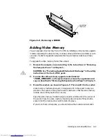
Страница 105: ... IURQW RI WKLV JXLGH 7R DFFHVV WKH YLGHR PHPRU XSJUDGH VRFNHW ODEHOHG 9 2B83 5 µ RQ WKH V VWHP ERDUG UHPRYH WKH H SDQVLRQ FDUG FDJH DV GHVFULEHG LQ 5HPRYLQJ WKH SDQVLRQ DUG DJHµ LQ KDSWHU 2ULHQW WKH PRGXOH DV VKRZQ LQ LJXUH 7KHQ LQVWDOO LW LQ WKH VRFNHW Video memory modules are keyed or designed to fit in the socket in only one direction The socket on the system board is notched so that the video ...

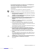
Страница 106: ... off the system remove the computer cover and reseat the video memory upgrade module in its socket 5XQ WKH 9LGHR 7HVW URXS LQ WKH HOO LDJQRVWLFV WR WHVW WKH QHZ YLGHR PHPRU For information on using the diagnostics and troubleshooting any problems that occur see the chapter titled Running the Dell Diagnostics in your Diagnostics and Troubleshooting Guide 8SJUDGLQJ WKH 0LFURSURFHVVRU To take advanta...

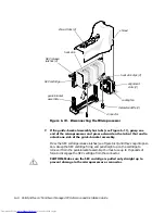
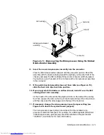
Страница 107: ...Gµ LQ KDSWHU 6HH LJXUH WR ORFDWH WKH PLFURSURFHVVRU FRQQHFWRU ODEHOHG 6 27 µ RQ WKH V VWHP ERDUG 5HPRYH WKH H LVWLQJ PLFURSURFHVVRU DVVHPEO IURP WKH FRQQHFWRU If the microprocessor connector is surrounded by a guide bracket assembly with out tabs see Figure 6 10 continue to step 5 If the microprocessor connector is surrounded by a guide bracket assembly with tabs at the top see Figure 6 11 skip to...

Страница 108: ...s see Figure 6 10 until they snap into posi tion Grasp the SEC cartridge firmly and pull straight up on the cartridge to remove it from the guide bracket assembly You must use up to 15 pounds of force to disengage the SEC cartridge from the connector 87 21 0DNH VXUH WKH 6 FDUWULGJH LV SXOOHG RQO VWUDLJKW XS WR SUHYHQW GDPDJH WR WKH PLFURSURFHVVRU RU FRQQHFWRU SEC release latches 2 heat sink SEC ca...

Страница 109: ... FOLSV EDFN LQWR SRVLWLRQ I RXU XSJUDGH NLW LQFOXGHV DQ DLUIORZ VKURXG LQVWDOO LW RYHU WKH 6 FDUWULGJH KHDW VLQN DVVHPEO Fit the mouth of the shroud into the alignment slots on the sides of the cooling fan Then squeeze the tabs on the top of the shroud and lower the shroud down until the clips under the tabs engage onto the top of the heat sink I QHFHVVDU FKDQJH WKH PLFURSURFHVVRU VSHHG MXPSHU VHW...

Страница 110: ...intains sys tem configuration date and time information in a special section of memory The operating life of the battery can extend up to ten years The battery may need replacing if an incorrect time or date is displayed during the boot routine along with a message such as 7LPH RI GD QRW VHW ª SOHDVH UXQ 6 783 SURJUDP or QYDOLG FRQILJXUDWLRQ LQIRUPDWLRQ ª SOHDVH UXQ 6 783 SURJUDP or 6WULNH WKH NH ...

Страница 111: ...YLQJ WKH SDQVLRQ DUG DJHµ LQ KDSWHU RFDWH WKH EDWWHU DQG UHPRYH LW The battery see Figure 6 1 is mounted in a socket labeled BATTERY in the front right corner of the system board as you face the front of the system 87 21 I RX SU WKH EDWWHU RXW RI LWV VRFNHW ZLWK D EOXQW REMHFW EH FDUHIXO QRW WR WRXFK WKH V VWHP ERDUG ZLWK WKH REMHFW 0DNH FHUWDLQ WKDW WKH REMHFW LV LQVHUWHG EHWZHHQ WKH EDWWHU DQG W...

Страница 112: ...formation on running the System Setup program Enter the correct time and date through the System Setup program s Time and Date categories Also use the copy you made in step 1 to restore the correct set tings for other system configuration information Then exit the System Setup program 7XUQ RII DQG XQSOXJ RXU FRPSXWHU HDYH WKH FRPSXWHU WXUQHG RII IRU DW OHDVW PLQXWHV IWHU PLQXWHV SOXJ LQ WKH FRPSXW...

Страница 113: ...ers available from Dell The two hard disk drive bays can each hold a 3 5 inch enhanced integrated drive electronics EIDE hard disk drive Together the bays can hold one 1 inch high or smaller drive and one 1 6 inch high or smaller drive The next three sections contain information that you will need in several of the instal lation procedures described later in the chapter The remaining sections of t...

Страница 114: ...lease tilt the bezel away from the chassis disengage the two retaining hooks at the bottom of the bezel and carefully pull the bezel away from the chassis To replace the bezel fit the two retaining hooks on the bezel into their corresponding slots at the bottom of the chassis Then rotate the top of the bezel toward the chassis until the top tabs snap into their corresponding slots on the bezel 5HP...

Страница 115: ... URQW H HO µ LWK RXU WKXPEV SUHVV LQ HDFK HQG RI WKH LQVHUW XQWLO LW VQDSV IUHH RI WKH EH HO VHH LJXUH LJXUH 5HPRYLQJ WKH URQW 3DQHO QVHUW IRU D QFK D To replace a front panel insert for a 5 25 inch bay work from inside the bezel Insert the two ring tabs one on each end of the insert over the posts on the inside of the bay opening and firmly press both ends of the insert into place see Figure 7 3 ...

Страница 116: ...e location of pin 1 on the drive s interface connector see the documentation that came with the drive When disconnecting an interface cable from the system board be sure to press in on the locking tabs on the cable connector before disconnecting the cable When attach ing an interface cable to the system board be sure that the locking tabs snap into place ensuring that the cable is firmly attached ...

Страница 117: ...CD ROM or tape drive that uses the secondary EIDE interface on the system board A CD ROM or tape drive that uses its own controller card To install a drive in a 5 25 inch drive bay follow these steps 8QSDFN WKH GULYH DQG SUHSDUH LW IRU LQVWDOODWLRQ 87 216 URXQG RXUVHOI E WRXFKLQJ DQ XQSDLQWHG PHWDO VXUIDFH RQ WKH EDFN RI WKH FRPSXWHU KHQ RX XQSDFN WKH GULYH GR QRW VHW LW RQ D KDUG VXUIDFH ZKLFK PD...

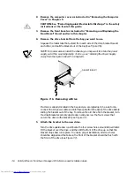
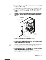
Страница 118: ...To do so see Rotating the Power Supply Away From the System Board in Chapter 5 LJXUH 5HPRYLQJ D ULYH If a drive is already installed in the bay and you are replacing it be sure to dis connect the DC power cable and interface cable from the back of the drive before sliding the bracket out of the bay To remove the old drive from the bracket turn the drive bracket assembly upside down and unscrew the...

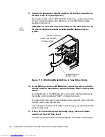
Страница 119: ...WR WKH GULYH ED XQWLO WKH GULYH VQDSV VHFXUHO LQWR SODFH VHH LJXUH Make sure that both bracket tabs snap into place in the drive bay LJXUH QVHUWLQJ WKH 1HZ ULYH QWR WKH ULYH D I RX DUH LQVWDOOLQJ D GULYH WKDW KDV LWV RZQ FRQWUROOHU FDUG LQVWDOO WKH FRQWUROOHU FDUG LQ DQ H SDQVLRQ VORW See Installing an Expansion Card in Chapter 6 RQQHFW D SRZHU FDEOH WR WKH SRZHU LQSXW FRQQHFWRU RQ WKH EDFN RI WKH...

Страница 120: ...SH GULYH RU 520 GULYH FRQQHFW WKH RWKHU HQG RI WKH LQWHUIDFH FDEOH WR WKH LQWHUIDFH FRQQHFWRU ODEHOHG µ RQ WKH V VWHP ERDUG For a diskette drive or non EIDE tape drive connect the cable from the drive to the interface connector labeled DSKT on the system board For a drive that comes with its own controller card connect the other end of the interface cable to the controller card Check all cable con...

Страница 121: ... If you installed a CD ROM drive see the documentation that came with the drive for instructions on loading device drivers and using the drive If it is an EIDE CD ROM drive test it by running all of the subtests in the IDE CD ROM Drives Test Group of the Dell Diagnostics If you installed a tape drive first verify that your diskette drive is still operat ing correctly by running all of the subtests...

Страница 122: ... instructions on obtaining technical assistance If you did not purchase the drive from Dell call the drive manufacturer With the two EIDE interface connectors on the system board your system can sup port up to four EIDE devices EIDE hard disk drives should be connected to the EIDE interface connector labeled IDE1 EIDE tape drives and CD ROM drives should be connected to the EIDE interface connecto...

Страница 123: ...its hinge tabs from the chassis slots LJXUH 5HPRYLQJ WKH DUG LVN ULYH UDFNHW 6OLGH WKH GULYH LQWR WKH FKRVHQ ED RI WKH EUDFNHW RULHQWHG VR WKDW WKH FRQQHFWRUV RQ WKH EDFN RI WKH GULYH ZLOO IDFH WKH EDFN RI WKH FKDVVLV ZKHQ WKH EUDFNHW LV UHLQVWDOOHG VHH LJXUH OLJQ WKH IRXU VFUHZ KROHV RI WKH GULYH DQG EUDFNHW QVHUW DQG WLJKWHQ WKH VFUHZV WKDW FDPH ZLWK RXU XSJUDGH NLW If you are installing a drive...

Страница 124: ... s hinge tabs into the chassis slots so that the tabs hook over the slots Then rotate the bracket toward the drive cage and fit the bracket s slid ing tab on the drive cage slide rail Slide the bracket into place Reinstall the screw you removed in step 4 LJXUH QVHUWLQJ WKH ULYH UDFNHW LQ WKH KDVVLV 1 6 inch drive screws 4 drive bracket sliding tab sliding tab hinge tabs drive cage slide rail chass...

Страница 125: ...DJH WR RXU V VWHP LJXUH WWDFKLQJ DUG LVN ULYH DEOHV I LW LV QRW DOUHDG FRQQHFWHG FRQQHFW WKH RWKHU HQG RI WKH FDEOH WR WKH FRQQHFWRU RQ WKH V VWHP ERDUG 87 21 RX PXVW PDWFK WKH FRORUHG VWULS RQ WKH FDEOH ZLWK SLQ RQ WKH FRQQHFWRU WR DYRLG SRVVLEOH GDPDJH WR RXU V VWHP To locate the IDE1 connector see Figure 6 1 5HSODFH WKH FRPSXWHU FRYHU 7KHQ UHFRQQHFW RXU FRPSXWHU DQG SHULSK HUDOV WR WKHLU SRZHU ...

Страница 126: ...arger than 2 gigabytes GB create a pri mary partition of 2 GB and divide the remaining capacity into partitions of 2 GB or less For example a system with a 2 5 GB hard disk drive would have a primary parti tion of 2 GB drive C and a second partition of 500 megabytes MB drive D Hard disk drives must be partitioned this way because MS DOS based operating sys tems including Windows NT when using a fi...

Страница 127: ...RUPDW RXU KDUG GLVN GULYH XQGHU WKH LQGRZV 17 LOH 6 VWHP 17 6 RX FDQQRW UHIRUPDW WKH GULYH IRU 06 26 ZLWKRXW ORVLQJ DOO 17 6 GDWD 6HH RXU LQGRZV 17 GRFXPHQWDWLRQ IRU GHWDLOV For the UNIX operating system refer to your UNIX documentation ...

Страница 128: ...7 16 Dell OptiPlex G1 Mini Tower Managed PC Reference and Installation Guide ...

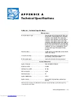
Страница 129: ...pported upgrades A slower compatibility speed can be set through the System Setup program Internal cache 32 KB first level 16 KB data cache 16 KB instruction cache L2 cache memory 512 KB pipelined burst four way set associative write back SRAM Math coprocessor internal to Pentium II microprocessor 6 VWHP QIRUPDWLRQ System chip set Intel 82440BX PCI AGP Data bus width 64 bits Address bus width 32 b...

Страница 130: ...tor size 120 pins PCI expansion card connector data width maximum 32 bits 0HPRU Architecture 64 bit nonparity noninterleaved DIMM sockets two DIMM capacities 32 64 and 128 MB SDRAM Standard RAM 32 MB minimum Maximum RAM 256 MB BIOS address F8000h ULYHV Externally accessible bays three 5 25 inch bays for diskette tape or CD ROM drives one 3 5 inch bay for a dis kette drive Internally accessible bay...

Страница 131: ... Diskette drive 34 pin connector 9LGHR Video type ATI Rage II C baseline AGP SVGA controller Video memory 2 MB standard upgradable to 4 MB Maximum resolution 1600 x 1200 pixels 256 colors H RPELQDWLRQV Ctrl Alt Del restarts reboots the system F2 starts System Setup program during POST only Ctrl Alt toggles microprocessor speeds on 101 key keyboard in MS DOS real mode only Ctrl Alt toggles micropro...

Страница 132: ...Activity indicator on optional integrated NIC connector yellow LED 3RZHU DC power supply Wattage 200 W Heat dissipation 913 BTUs fully loaded system without monitor Voltage 90 to 135 V at 60 Hz 180 to 265 V at 50 Hz Backup battery 3 V CR2032 coin cell 3K VLFDO Height 44 4 cm 17 5 inches Width 20 6 cm 8 1 inches Depth 43 7 cm 17 2 inches Weight 15 kg 33 0 lb or more depending on options installed 7...

Страница 133: ... at 1 octave min Maximum shock Operating bottom half sine pulse with a change in velocity of 20 inches sec 50 8 cm sec Storage 27 G faired square wave with a velocity change of 200 inches sec 508 cm sec Altitude Operating 16 to 3048 m 50 to 10 000 ft Storage 16 to 10 600 m 50 to 35 000 ft 7DEOH 7HFKQLFDO 6SHFLILFDWLRQV FRQWLQXHG NOTE For the full name of an abbreviation or acronym used in this tab...

Страница 134: ...A 6 Dell OptiPlex G1 Mini Tower Managed PC Reference and Installation Guide ...

Страница 135: ...peration These messages alert you to problems that prevent the ICU from running correctly as well as informing you of resource conflicts that prevent the configuration of various cards in your com puter If you receive a message from the ICU see Table B 1 for suggestions on resolving any problems indicated by the message 7DEOH RQILJXUDWLRQ 8WLOLW 0HVVDJHV 0HVVDJH 3UREDEOH DXVH RUUHFWLYH FWLRQ 2XW R...

Страница 136: ...HP 8Q FRQILJXUHG FDUGV DUH PDUNHG FRQ ILJ HUU LQ WKH OLVW RI FRQILJ XUHG FDUGV The Configuration Man ager or the ICU cannot configure at least one Plug and Play expansion card because of resource conflicts with one or more cards You must reconfigure the conflicting card s To find the conflicting card perform the following steps 6HOHFW WKH 3OXJ DQG 3OD H SDQVLRQ FDUG PDUNHG ZLWK FRQILJ HUU DQG WKHQ...

Страница 137: ...our system for these settings to take effect 7KH ORDGHG FDUG LV QRW D FDWHJRU FDUG 3UHVV 2 WR SURFHHG The category you have chosen is not the correct category under which to add this card Select OK The ICU automatically opens the correct category s dialog box Continue the proce dure for adding the card as described in Adding a Listed Card or Adding an Unlisted Card in Chapter 3 1R PRUH 0 YDO XHV F...

Страница 138: ...or instructions If FRQIOLFWLQJBFDUG is not the system board remove it from the computer See Removing a Card in Chapter 3 for instructions Remove all expansion cards from the ICU and then add them back one at a time beginning with the new card and resolving resource con flicts as they arise See Removing a Card and Adding a Listed Card or Adding an Unlisted Card in Chapter 3 for instructions If you ...

Страница 139: ... procedure QVHUW WKH RULJLQDO 6 RQILJXUDWLRQ 8WLOLW LVNHWWH LQWR GULYH KDQJH WR WKH GE VXEGLUHFWRU RQ WKH GLV NHWWH GULYH For example type cd D GE 8VH D WH W HGLWRU WR VHDUFK WKH LFX QG ILOH IRU WKH FDUG RI WKH FDUG RX ZDQW WR DGG RU PRGLI The name of the configuration file is part of this card ID For example if the card ID is ICU0200 the configuration file is icu0200 cfg RS WKH FRQILJXUDWLRQ ILOH...

Страница 140: ...nflicts You added an ISA expansion card selected Advanced and chose resource values different from the card s defaults Make note of the new card configuration shown in the Card Resource Usage dialog box displayed after this message Change jumper settings on the ISA expansion card to match the new card configuration 7DEOH RQILJXUDWLRQ 8WLOLW 0HVVDJHV FRQWLQXHG 0HVVDJH 3UREDEOH DXVH RUUHFWLYH FWLRQ ...

Страница 141: ...all failed with an internal error The most likely cause is an incom patibility between the BIOS and the Configura tion Manager See the chapter titled Getting Help in your Diagnostics and Troubleshooting Guide for instructions on obtaining techni cal assistance 5525 RXOG QRW UHDG 196 UURU QWHUQDO UURU RGH An attempt to read the NVRAM failed See the chapter titled Getting Help in your Diagnostics an...

Страница 142: ...emov ing an Expansion Card in Chapter 6 and then return to this procedure 5HLQVWDOO WKH 3OXJ DQG 3OD H SDQVLRQ FDUG Follow steps 5 through 9 of Installing an Expansion Card in Chapter 6 and then return to this procedure If you still receive the error message con tact the manufacturer of the Plug and Play expansion card for assistance 7DEOH RQILJXUDWLRQ 0DQDJHU 0HVVDJHV FRQWLQXHG 0HVVDJH 3UREDEOH D...

Страница 143: ...nd Play or PCI expansion cards that could not be configured should be marked FRQILJ HUU on the list of cards in the ICU window 6HOHFW WKH 6 VWHP 5HVRXUFHV RSWLRQ IURP WKH 9LHZ PHQX The System Resource Usage dialog box displays all resources currently used by the system 6HOHFW RQH RI WKH UHVRXUFHV XVHG E RXU 3OXJ DQG 3OD RU 3 H SDQVLRQ FDUG DQG FOLFN 8VHG DUG The Card Resources Usage dialog box ide...

Страница 144: ...KH 8 UHVROYLQJ DQ UHVRXUFH FRQIOLFWV DV WKH DULVH See Adding a Listed Card in Chapter 3 for instructions If your Plug and Play or PCI expansion card is not automatically configured when you reboot the system with all other cards removed you should contact the manufac turer of the card or see the chapter titled Getting Help in your Diagnostics and Trou bleshooting Guide 51 1 RRW HYLFH FRQIOLFW GHWH...

Страница 145: ...l device Once you have determined your system s FCC classification read the appropriate FCC notice Note that FCC regulations provide that changes or modifications not expressly approved by Dell Computer Corporation could void your authority to operate this equipment 1RWLFH ERXW 6KLHOGHG DEOHV 8VH RQO VKLHOGHG FDEOHV IRU FRQQHFWLQJ SHULSKHUDOV WR DQ HOO GHYLFH WR UHGXFH WKH SRVVLELOLW RI LQWHUIHUHQ...

Страница 146: ...erence by one or more of the following measures Reorient the receiving antenna Relocate the computer with respect to the receiver Move the computer away from the receiver Plug the computer into a different outlet so that the computer and the receiver are on different branch circuits If necessary consult a representative of Dell Computer Corporation or an experienced radio television technician for...

Страница 147: ...ndicated on the registration label digital apparatus meets the requirements of the Canadian Interference Causing Equipment Regulations Cet appareil numérique de la Classe B ou Classe A si ainsi indiqué sur l étiquette d enregistration respecte toutes les exigences du Reglement sur le Materiel Brouilleur du Canada This device belongs to category B devices as described in EN 55022 unless it is speci...

Страница 148: ...rostatic discharge requirements Severity level 3 IEC 801 3 Electromagnetic compatibility for industrial process measurement and control equipment Part 3 Radiated electromagnetic field requirements Severity level 2 IEC 801 4 Electromagnetic compatibility for industrial process measurement and control equipment Part 4 Electrical fast transient burst requirements Severity level 2 EN60950 1992 Amd 1 1...

Страница 149: ...e instruction manual RUHDQ 5HJXODWRU 1RWLFH To determine which classification Class A or B applies to your computer system or other Dell digital apparatus examine all registration labels located on the bottom or back panel of your computer or other Dell digital apparatus on card mounting brack ets and on the cards themselves If any one of the labels carries a Class A rating your entire system is c...

Страница 150: ...N HOJB EP LP LJFN 8TQÍ QSBDVK DF F TPC VS E FOJB LPNQVUFS NPOJUPS ESVLBSLB QPXJOOZ CZÀ BTJMBOF UFHP TBNFHP ySÍE B OTUBMBDKB FMFLUSZD OB QPNJFT D FOJB QPXJOOB BXJFSBÀ X QS FXPE JF GB PXZN SF FSXPX PDISPOÄ QS FE XBSDJBNJ X QPTUBDJ CF QJFD OJLB P XBSUPvDJ OBNJPOPXFK OJF XJÄLT FK OJ BNQFSÍX 8 DFMV DB LPXJUFHP XZ D FOJB VS E FOJB TJFDJ BTJMBOJB OBMF Z XZK À XUZD LÄ LBCMB BTJMBK DFHP HOJB ELB LUÍSF QPXJ...

Страница 151: ...FSB X DJBTOZN NJFKTDV CF NP MJXPvDJ DZSLVMBDKJ QPXJFUS B XPLÍ OJFHP 120 QIRUPDWLRQ 0H LFR 2QO The following information is provided on the device s described in this document in compliance with the requirements of the official Mexican standards NOM 024 Exporter Dell Computer Corporation One Dell Way Round Rock TX 78682 Importer Dell Computer de México S A de C V Rio Lerma No 302 4 Piso Col Cuauhte...

Страница 152: ... Norma Oficial Mexicana NOM 024 4 1RWLFH IRU 7DLZDQ 2QO Exportador Dell Computer Corporation One Dell Way Round Rock TX 78682 Importador Dell Computer de México S A de C V Rio Lerma No 302 4 Piso Col Cuauhtemoc 16500 México D F Embarcar a Dell Computer de México S A de C V al Cuidado de Kuehne Nagel de México S de R I Avenida Soles No 55 Col Peñon de los Baños 15520 México D F Tensión alimentación...

Страница 153: ...system is shipped from Dell accessories or parts added to a Dell system through Dell s system integration department accessories or parts that are not installed in the Dell factory or DellWare products Monitors key boards and mice that are Dell branded or that are included on Dell s standard price list are covered under this warranty all other monitors keyboards and mice including those sold throu...

Страница 154: ...inental U S or Canada where applicable Shipments to other locations will be made freight collect Dell will include a prepaid shipping container with each replacement part for your use in returning the replaced part to Dell Replacement parts are new or reconditioned Dell may provide replacement parts made by various manufacturers when supplying parts to you The warranty term for a replacement part ...

Страница 155: ...user customer who bought products directly from a Dell company you may return them to Dell up to 30 days from the date of invoice for a refund of the product purchase price if already paid This refund will not include any shipping and handling charges shown on your invoice If you are an organization who bought the products from Dell under a written agreement with Dell there may be different terms ...

Страница 156: ...D 4 Dell OptiPlex G1 Mini Tower Managed PC Reference and Installation Guide ...

Страница 157: ...ce category 2 7 booting the computer system 2 7 cables connector types 7 4 DC power 5 6 7 3 drive interface 5 6 5 8 7 3 cache secondary 1 2 card edge connector 7 4 cautions xi CD ROM audio interface connector 6 2 chassis intrusion alarm 1 8 Chassis Intrusion option 2 12 chassis intrusion switch connector 6 2 location 5 8 COM port designations 2 9 computer booting 2 7 features 1 1 hung system 1 9 i...

Страница 158: ...nagement Interface See DMI diagnosing problems 1 13 diagnostics system 1 4 DIMMs about 6 7 capacities supported 1 2 installing 6 7 6 10 removing 6 10 sockets 6 2 Diskette Drive A and Diskette Drive B categories 2 5 Diskette Drive A option 2 8 diskette drives connecting 7 3 7 4 installing 7 5 interface connector 6 2 turning off built in controller 2 11 types sizes and capacities 2 5 Diskette Interf...

Страница 159: ...removing with ICU 3 13 resources viewing 3 13 unlisted cards 3 9 with diskette drive controller 2 11 with hard disk drive controller 2 10 with ports 2 9 expansion card cage location 5 8 removing and replacing 5 12 external drive bays 5 8 failures 1 13 filler bracket 6 5 fixed disk See drives EIDE hard disk drives fixing problems 1 13 floppy drives See diskette drives formatting EIDE hard disk driv...

Страница 160: ...tecture See ISA inserts front panel 7 2 installing DIMMs 6 7 6 10 drives 7 5 expansion cards 6 4 microprocessor 6 12 system battery 6 16 integrated devices 4 1 Integrated Devices category 2 9 Intel PIIX4e INF Update Installer 1 11 interface cables about 5 6 7 3 connectors 6 2 7 4 internal drive cage 5 8 ISA Configuration Utility See ICU ISA expansion cards See also expansion cards about 6 2 config...

Страница 161: ...on 2 9 MS DOS network driver 4 7 1 network drivers MS DOS 4 7 Windows 95 4 5 Windows for Workgroups 4 6 Windows NT 3 5x 4 4 Windows NT 4 0 4 3 network interface controller See NIC NIC about 4 1 configuring 4 2 connector 4 2 5 8 6 2 link integrity 4 2 MS DOS driver 4 7 network cable requirements 4 2 Windows 95 driver 4 5 Windows for Workgroups driver 4 6 Windows NT 3 5x driver 4 4 Windows NT 4 0 dr...

Страница 162: ...board Errors category 2 13 Reserved Memory category 2 8 return policy D 3 ribbon cables 5 8 7 5 riser board connector 6 2 expansion card connectors 6 3 6 safety instructions for preventing ESD vi for working inside computer v general iii health considerations iv list 5 1 SEC cartridge location 6 2 security 1 8 2 12 2 15 See also setup password system password security cable slot location 1 8 5 8 u...

Страница 163: ...screen information 2 1 entering 2 1 error messages 2 21 key functions 2 2 navigation keys 2 3 screen 2 4 setup password feature 2 19 system configuration information 2 1 system password feature 2 15 using the program 2 2 System Time category 2 5 system See computer 7 tape drives installing 7 3 interface cable 5 8 interface connector 6 2 technical assistance 1 13 technical specifications A 1 tools ...

Страница 164: ...nstallation Guide Wakeup On LAN 1 2 1 8 Wakeup on LAN category 2 13 warnings xi 5 1 warranty information x D 1 Windows 95 network driver 4 5 reinstalling 1 11 Windows for Workgroups NIC driver 4 6 Windows NT 3 5x NIC driver 4 4 Windows NT 4 0 NIC driver 4 3 ...

Отзывы: