


Desktop
Small form factor
two 120-pin connectors
one 120-pin connector
PCI Express x1
Mini-tower
Desktop
Small form factor
data width (maximum) — one PCI Express
lane
one 36-pin connector
not applicable
not applicable
PCI Express x16
one 164-pin connector
data width (maximum) — 16 PCI Express
lanes
Serial ATA
Mini-tower
Desktop
Small form factor
four 7-pin connectors
three 7-pin connectors
three 7-pin connectors
Memory
four 240-pin connectors
Internal USB device
one 10-pin connector (supports two USB
ports)
Processor fan
one 5-pin connector
Hard-drive fan
one 5-pin connector
Front panel control
one 40-pin connector
Processor
one 775-pin connector
Power 12V
one 4-pin connector
Power
one 24-pin connector
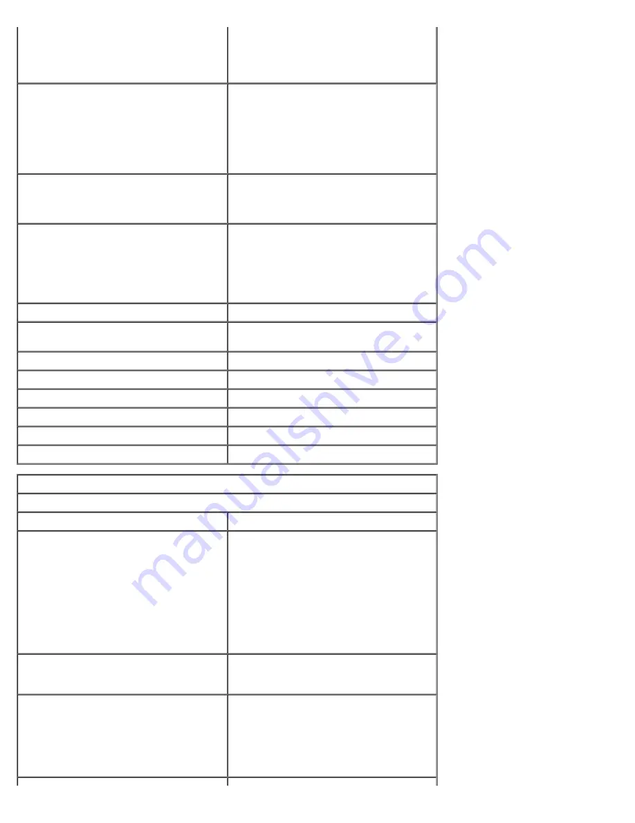
Controls and Lights
Front of the computer
Power button
push button
Power light
blinking green — indicates that the
computer is in sleep state
solid green — indicates that the computer
is in power-on state
blinking amber — indicates a problem
with the system board
solid amber — indicates that the system
board is unable to initialize
Drive activity light
blinking green — indicates that the
computer is reading data from or writing
data to the hard drive
Network connectivity light
green — indicates that a good connection
exists between the network and the
computer
off (no light) — indicates that the
computer is not detecting a physical
connection to the network
Содержание OptiPlex 780
Страница 2: ......
Страница 26: ...7 Lift the hard drive and remove it from the system ...
Страница 29: ...4 Pull up on the drive release latch and then slide the floppy drive towards the back of the computer ...
Страница 30: ...5 Lift the floppy drive up and away from the computer ...
Страница 37: ...7 Release the processor power connector cable from routing guides under the system board ...
Страница 38: ...8 Remove the screws that secure the power supply to the back of the chassis ...
Страница 40: ...10 Lift the power supply up and away from the computer ...
Страница 43: ...4 Lift the fan and remove it from the computer ...
Страница 44: ...Replacing the Fan To replace the fan perform the above steps in reverse order Back to Contents Page ...
Страница 46: ...6 Disconnect the fan power cable 7 Disconnect the main power cable from the system board ...
Страница 47: ...8 Disconnect the IO panel cable ...
Страница 48: ...9 Disconnect the optical drive data cable from the system board ...
Страница 49: ...10 Disconnect the hard drive data cable from the system board ...
Страница 50: ...11 Disconnect the processor power cable ...
Страница 51: ...12 Remove the screws that secure the system board to the computer chassis ...
Страница 52: ...13 Remove the heat sink assembly bracket ...
Страница 56: ...4 Lift the drive release latch and then slide the drive towards the back of the computer ...
Страница 57: ...5 Lift and remove the drive from the computer ...
Страница 61: ...6 Lift the hard drive and remove it from the computer ...
Страница 64: ...4 Gently pull the riser cage handle and lift the riser cage up and away from the computer ...
Страница 65: ...5 On the riser cage rotate the card retention latch upward ...
Страница 69: ......
Страница 71: ...3 Rotate the heat sink upwards 4 Lift the heat sink and remove it from the computer ...
Страница 73: ...6 Lift the processor cover ...
Страница 74: ...7 Remove the processor from the computer ...
Страница 79: ...4 Gently rotate the IO panel away from the computer and then remove it from the computer ...
Страница 80: ...Replacing the IO Panel To replace the IO panel perform the above steps in reverse order Back to Contents Page ...