Dell Olympus O-T600 Скачать руководство пользователя страница 75

NOTE:

 For example, if you populate socket A1 for processor 1, then populate socket B1 for processor 2, and so on.

Mixing of more than two memory module capacities in one system is not supported.

Unbalanced memory configurations will result in a performance loss so always populate memory channels identically with
identical DIMMs for best performance.

Populate six identical memory modules per processor (one DIMM per channel) at a time to maximize performance.

DIMM population update for Performance Optimized mode with quantity of 4 and 8 DIMMs per processor.

When the DIMM quantity is 4 per processor, the population is slot 1, 2, 4, 5.

When the DIMM quantity is 8 per processor, the population is slot 1, 2, 4, 5, 7, 8, 10, 11 (2-2-2 platforms).

NVDIMM-N memory module installation guidelines

The following are the recommended guidelines for installing NVDIMM-N memory modules:

Each system supports memory configurations with 1, 2, 4, 6, or 12 NVDIMM-Ns.

Supported configurations have dual processors and a minimum of 12x RDIMMs.

Maximum of 12 NVDIMM-Ns can be installed in a system.

NVDIMM-Ns or RDIMMs must not be mixed with LRDIMMs.

DDR4 NVDIMM-Ns must be populated only on the black release tabs on processor 1 and 2.

All slots on configurations 3, 6, 9, and 12 can be used, but a maximum of 12 NVDIMM-Ns can be installed in a system.

NOTE:

 NVDIMM-N memory slots are not hot-pluggable.

For more information about the supported NVDIMM-N configurations, see the 

NVDIMM-N User Guide

 at 

www.dell.com/

poweredgemanuals

.

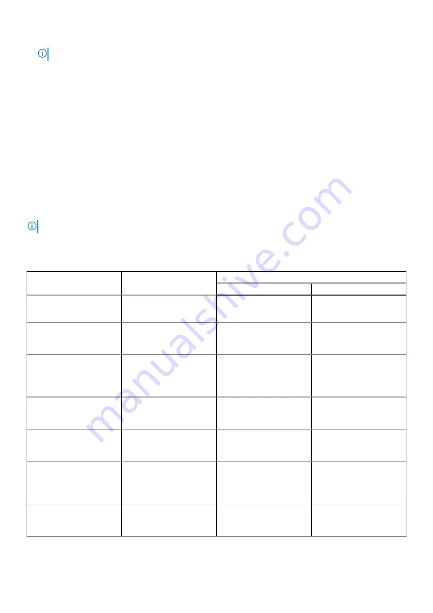
Table 15. Supported NVDIMM-N for dual processor configurations 

Configuration

Description

Memory population rules

RDIMMs

NVDIMM-N

Configuration 1

12x 16 GB RDIMMs, 1x
NVDIMM-N

Processor1 {A1, 2, 3, 4, 5, 6}
Processor2 {B1, 2, 3, 4, 5, 6}

Processor1 {A7}

Configuration 2

12x 32 GB RDIMMs, 1x
NVDIMM-N

Same for all 12x
RDIMM configurations. See
Configuration 1.

Processor1 {A7}

Configuration 3

23x 32 GB RDIMMs, 1x
NVDIMM-N

Processor1 {A1, 2, 3, 4, 5, 6, 7,
8, 9, 10, 11, 12}
Processor2 {B1, 2, 3, 4, 5, 6,
7, 8, 9, 10, 11}

Processor2 {B12}

Configuration 4

12x 16 GB RDIMMs, 2x
NVDIMM-Ns

Same for all 12x
RDIMM configurations. See
Configuration 1.

Processor1 {A7}

Processor2 {B7}

Configuration 5

12x 32 GB RDIMMs, 2x
NVDIMM-Ns

Same for all 12x RDIMM
configurations.  See
Configuration 1.

Processor1 {A7}

Processor2 {B7}

Configuration 6

22x 32 GB RDIMMs, 2x
NVDIMM-Ns

Processor1 {A1, 2, 3, 4, 5, 6, 7,
8, 9, 10, 11}
Processor2 {B1, 2, 3, 4, 5, 6,
7, 8, 9, 10, 11}

Processor1 {A12}

Processor2 {B12}

Configuration 7

12x 16 GB RDIMMs, 4x
NVDIMM-Ns

Same for all 12x
RDIMM configurations. See
Configuration 1.

Processor1 {A7, A8}

Processor2 {B7, B8}

74

Installing and removing system components

Содержание Olympus O-T600

Страница 1: ...OverlandTandberg com WHITE PAPER Olympus O T600 installation and service manual Dell Technologies ...

Страница 2: ...Dell EMC PowerEdge T640 Installation and Service Manual Regulatory Model E47S Series Regulatory Type E47S001 December 2020 Rev A14 ...

Страница 3: ...tial damage to hardware or loss of data and tells you how to avoid the problem WARNING A WARNING indicates a potential for property damage personal injury or death 2017 2021 Dell Inc or its subsidiaries All rights reserved Dell EMC and other trademarks are trademarks of Dell Inc or its subsidiaries Other trademarks may be trademarks of their respective owners ...

Страница 4: ... install the operating system 25 Methods to download firmware and drivers 25 Downloading drivers and firmware 26 Chapter 3 Installing and removing system components 27 Safety instructions 27 Before working inside your system 28 After working inside your system 28 Optional front bezel 28 Removing the front bezel 28 Installing the front bezel 29 System feet 30 Removing the system feet 30 Installing ...

Страница 5: ... specifications 55 Cooling fan matrix 56 Removing a middle or rear cooling fan 56 Installing a middle or rear cooling fan 57 Removing the right external fan 58 Installing the right external fan 59 Cooling fan middle fan assembly 60 Removing the middle cooling fan assembly 60 Installing the middle cooling fan assembly 60 Flex bays 61 Removing a NVMe drive bay or flex bay 61 Installing a NVMe drive ...

Страница 6: ...ional GPU card 95 Removing the optional GPU card 95 Installing the optional GPU card 96 NVLink bridge 97 Removing the optional NVLink bridge 97 Installing the optional NVLink bridge 98 M 2 SSD module 99 Removing the M 2 SSD module 99 Installing the M 2 SSD module 100 Optional MicroSD or vFlash card 101 Removing the MicroSD card 101 Installing the MicroSD card 102 Optional IDSDM or vFlash module 10...

Страница 7: ...d 128 Installing the main power interposer board 129 Converting the system from tower mode to rack mode 129 Converting the system from tower mode to rack mode 129 Chapter 4 System diagnostics 132 Dell Embedded System Diagnostics 132 Running the Embedded System Diagnostics from Boot Manager 132 Running the Embedded System Diagnostics from the Dell Lifecycle Controller 132 System diagnostic controls...

Страница 8: ...upply units Drive configurations 8 x 3 5 inch or 8 x 2 5 inch in 3 5 inch carrier SAS SATA SSD drives 18 x 3 5 inch SAS SATA SSD drives 16 x 2 5 inch SAS SATA SSD drives 16 x 2 5 inch SAS SATA SSD drives with 8 x NVME drives 32 x 2 5 inch SAS SATA SSD drives For more information see the Dell EMC PowerEdge T640 Technical Specifications on the product documentation page Topics Supported configuratio...

Страница 9: ...Supported configurations Figure 1 Supported configurations of the PowerEdge T640 8 Dell EMC PowerEdge T640 overview ...

Страница 10: ... inch drive tower system 1 Power button 2 Information tag 3 iDRAC Quick Sync 2 wireless indicator optional 4 Status LED indicators 5 System health and system ID indicator 6 USB port USB 2 0 compliant 7 USB port USB 3 0 compliant 8 iDRAC Direct Micro AB USB port 9 Optical drive optional 10 Drive slots Dell EMC PowerEdge T640 overview 9 ...

Страница 11: ...ion tag 3 iDRAC Quick Sync 2 wireless indicator optional 4 Status LED indicators 5 System health and system ID indicator 6 USB port USB 2 0 compliant 7 USB port USB 3 0 compliant 8 iDRAC Direct Micro AB USB port 9 Optical drive optional 10 Drive slots 10 Dell EMC PowerEdge T640 overview ...

Страница 12: ...E The indicators display solid amber if any error occurs Figure 5 Status LED indicators Table 1 Status LED indicators and descriptions Icon Description Condition Corrective action PCIe indicator The indicator turns solid amber if a PCIe card experiences an error Restart the system Update any required drivers for the PCIe card Reinstall the card If the problem persists see Getting help NOTE For mor...

Страница 13: ...cted If the problem persists see Getting help Drive indicator The indicator turns solid amber if there is a drive error Check the System Event Log to determine if the drive has an error Run the appropriate Online Diagnostics test Restart the system and run embedded diagnostics ePSA If the drives are configured in a RAID array restart the system and enter the host adapter configuration utility prog...

Страница 14: ...Sync 2 feature is configured to be disabled by iDRAC If the problem persists see the Getting help section For more information see www dell com idracmanuals www dell com operatingsystemmanuals Solid amber Indicates that the system is in fail safe mode Restart the system If the problem persists see the Getting help section Blinking amber Indicates that the iDRAC Quick Sync 2 hardware is not respond...

Страница 15: ...cators 1 Drive activity LED indicator 2 Drive status LED indicator 3 Drive capacity label NOTE If the drive is in the Advanced Host Controller Interface AHCI mode the status LED indicator does not turn on Table 5 Drive indicator codes Drive status indicator code Condition Flashes green twice per second Identifying drive or preparing for removal Off Drive ready for removal NOTE The drive status ind...

Страница 16: ...iew of the tower configuration 1 PCIe expansion card slots 2 System ID button indicator 3 VGA port 4 Serial port 5 iDRAC9 dedicated network port 6 USB 2 0 port 2 7 PCIe expansion card slots 8 NIC port 2 9 System Identification connector 10 USB 3 0 port 4 11 Power supply unit 2 Dell EMC PowerEdge T640 overview 15 ...

Страница 17: ...3 Left external fan available only with GPGPU configuration For more information see the Dell EMC PowerEdge T640 Technical Specifications on the product documentation page NIC indicator codes Each NIC on the back of the system has indicators that provide information about the activity and link status The activity LED indicator indicates if data is flowing through the NIC and the link LED indicator...

Страница 18: ...nt handle that serves as an indicator The DC PSUs have an LED that serves as an indicator The indicator shows whether power is present or if a power fault has occurred Figure 12 AC PSU status indicator 1 AC PSU status indicator handle Table 7 AC PSU status indicator codes Power indicator codes Condition Green A valid power source is connected to the PSU and the PSU is operational Blinking amber In...

Страница 19: ...reen A valid power source is connected to the PSU and the PSU is operational Blinking amber Indicates a problem with the PSU Not illuminated Power is not connected to the PSU Blinking green When hot plugging a PSU the PSU indicator blinks green This indicates that there is a PSU mismatch with respect to efficiency feature set health status or supported voltage CAUTION If two PSUs are installed bot...

Страница 20: ...Service Tag Alternatively the information may be on a sticker on the chassis of the system The mini Enterprise Service Tag EST is found on the back of the system This information is used by Dell to route support calls to the appropriate personnel Figure 14 Locating Service Tag of your system 1 information tag top view 2 information tag back view 3 OpenManage Mobile OMM label 4 iDRAC MAC address an...

Страница 21: ...Figure 16 Configuration and layout 20 Dell EMC PowerEdge T640 overview ...

Страница 22: ...Figure 17 Electrical overview Dell EMC PowerEdge T640 overview 21 ...

Страница 23: ...Figure 18 Memory information 22 Dell EMC PowerEdge T640 overview ...

Страница 24: ...Figure 19 System tasks Dell EMC PowerEdge T640 overview 23 ...

Страница 25: ... Integrated Dell Remote Access Controller iDRAC is designed to make system administrators more productive and improve the overall availability of Dell systems iDRAC alerts administrators about system issues and enables them to perform remote system management This reduces the need for physical access to the system Options to set up iDRAC IP address To enable communication between your system and i...

Страница 26: ... licenses see the latest Integrated Dell Remote Access Controller User s Guide at www dell com poweredgemanuals You can also access iDRAC by using RACADM For more information see the RACADM Command Line Interface Reference Guide at www dell com poweredgemanuals Options to install the operating system If the system is shipped without an operating system install a supported operating system by using...

Страница 27: ... drivers and firmware Dell EMC recommends that you download and install the latest BIOS drivers and systems management firmware on your system Prerequisites Ensure that you clear the web browser cache before downloading the drivers and firmware Steps 1 Go to www dell com support home 2 In the Drivers Downloads section type the Service Tag of your system in the Enter a Service Tag or product ID box...

Страница 28: ...er GPU card holder optional Expansion cards Optional GPU card NVLink bridge M 2 SSD module Optional MicroSD or vFlash card Optional IDSDM or vFlash module Backplane Backplane cabling Integrated storage controller card System battery Optional internal USB memory key Control panel assembly Trusted Platform Module System board Power interposer boards Converting the system from tower mode to rack mode...

Страница 29: ... inside your system Prerequisites Follow the safety guidelines listed in Safety instructions on page 27 Steps 1 Turn off the system including all attached peripherals 2 Disconnect the system from the electrical outlet and disconnect the peripherals 3 Lay the system on its side 4 Remove the system cover After working inside your system Prerequisites Follow the safety guidelines listed in Safety ins...

Страница 30: ...fety instructions on page 27 Steps 1 Locate and remove the bezel key NOTE There are two bezel keys attached to the back of the bezel 2 Insert the bezel tabs into the slots in the chassis 3 Press the release latch and push the bezel toward the system until the bezel locks into place 4 Using the key lock the bezel Installing and removing system components 29 ...

Страница 31: ...r when you are replacing the system feet with the wheel assembly 1 Follow the safety guidelines listed in Safety instructions on page 27 2 Place the system on its side on a flat stable surface 3 Rotate the system feet inward Steps Using the Phillips 2 screwdriver remove the screw that secures the foot to the base of the system a Repeat the above step for the 3 remaining feet 30 Installing and remo...

Страница 32: ...se injury to the user or damage to the system 1 Follow the safety guidelines listed in Safety instructions on page 27 2 Place the system on its side on a flat stable surface Steps 1 Align the three tabs on the system foot with the three slots on the base of the system 2 Using the Phillips 2 screwdriver secure the screw that secures the foot to the base of the system a Repeat the above steps to ins...

Страница 33: ... 27 2 Place the system on a flat stable surface Steps 1 Using the Phillips 2 screwdriver loosen the captive screw that secures the front wheel unit to the base of the system 2 Push the front wheel unit toward the rear of the system to release the retention hooks and pull out the front wheel unit 3 Loosen the screw that secures the back wheel unit to the base of the chassis 4 Push the rear wheel un...

Страница 34: ...rear wheel unit with the two slots on the base of the system and insert the hooks into the slots 2 Push the rear wheel unit toward the back of the system and using a Phillips 2 screwdriver secure the unit in place using a single screw 3 Align the two retention hooks on the front wheel unit with the two slots on the base of the system and insert the hooks into the slots 4 Push the front wheel unit ...

Страница 35: ...requisites 1 Follow the safety guidelines listed in Safety instructions on page 27 2 If installed remove the front bezel CAUTION To maintain proper system cooling drive blanks must be installed in all empty drive slots CAUTION Mixing drive blanks from previous generations of PowerEdge servers is not supported Steps Press the release button and slide the drive blank out of the drive slot 34 Install...

Страница 36: ... 1 Follow the safety guidelines listed in Safety instructions on page 27 2 If installed remove the front bezel CAUTION Mixing drive blanks from previous generations of PowerEdge servers is not supported Steps Insert the drive blank into the drive slot and push the blank until the release button clicks into place Figure 27 Installing a drive blank Installing and removing system components 35 ...

Страница 37: ...ng see the documentation for the storage controller card to ensure that the host adapter is configured correctly to support drive removal and insertion CAUTION Mixing drives from previous generations of PowerEdge servers is not supported CAUTION To prevent data loss ensure that your operating system supports drive installation See the documentation supplied with your operating system Steps 1 Press...

Страница 38: ...nsure that your operating system supports hot swap drive installation See the documentation supplied with your operating system CAUTION When a replacement hot swappable drive is installed and the system is powered on the drive automatically begins to rebuild Ensure that the replacement drive is blank or contains data that you wish to overwrite Any data on the replacement drive is immediately lost ...

Страница 39: ... from the drive carrier Next steps 1 Installing the drive into the drive carrier Installing a drive into the drive carrier Prerequisites Follow the safety guidelines listed in Safety instructions on page 27 CAUTION Mixing drive carriers from other generations of PowerEdge servers is not supported NOTE When installing a drive into the drive carrier ensure that the screws are torqued to 4 in lbs Ste...

Страница 40: ...3 5 inch drive carrier Prerequisites 1 Follow the safety guidelines listed in Safety instructions on page 27 2 If installed remove the front bezel 3 Remove the drive carrier Steps 1 Using a Phillips 1 screwdriver remove the screws from the rails on the drive carrier NOTE If the hard drive or SSD carrier has Torx screw use Torx 6 for 2 5 inch drive or Torx 8 for 3 5 inch drive screwdriver to remove...

Страница 41: ...nch drive adapter Steps 1 Insert the 3 5 inch drive adapter into the 3 5 inch drive carrier with the connector end of the drive toward the back of the 3 5 inch drive carrier 2 Align the screw holes on the 3 5 inch drive adapter with the holes on the 3 5 inch drive carrier 3 Using a Phillips 1 screwdriver secure the 3 5 inch drive adapter to the 3 5 inch carrier NOTE If the hard drive or SSD carrie...

Страница 42: ...ge 27 2 Remove the 3 5 inch drive adapter from the 3 5 inch drive carrier NOTE A 2 5 inch drive is installed in a 3 5 inch drive adapter which is then installed in the 3 5 inch drive carrier Steps 1 Using a Phillips 2 screwdriver remove the screws from the side of the 3 5 inch drive adapter NOTE If the hard drive or SSD carrier has Torx screw use Torx 6 screwdriver to remove the drive 2 Remove the...

Страница 43: ...uisites 1 Follow the safety guidelines listed in Safety instructions on page 27 2 Remove the 3 5 inch drive adapter from the 3 5 inch hot swappable drive carrier Steps 1 Align the screw holes on the 2 5 inch drive with the screw holes on the 3 5 inch drive adapter 2 Using a Phillips 2 screwdriver secure the 2 5 inch drive to the 3 5 inch drive adapter 42 Installing and removing system components ...

Страница 44: ...e Extended Power Performance EPP label Mixing PSUs from previous generations of PowerEdge servers is not supported even if the PSUs have the same power rating Mixing PSUs will result in mismatch condition or failure to turn the system on NOTE Titanium PSU is nominally rated for 200 V AC to 240 V AC input only NOTE When two identical PSUs are installed power supply redundancy 1 1 with redundancy or...

Страница 45: ... 20 percent of PSU rated power wattage then the redundant PSU is switched to the sleep state You can configure the hot spare feature by using the iDRAC settings For more information see the iDRAC User s Guide available at Dell com idracmanuals Removing a power supply unit blank Prerequisites Follow the safety guidelines listed in Safety instructions on page 27 Steps If you are installing a second ...

Страница 46: ...l operation On power redundant systems remove and replace only one PSU at a time in a system that is powered on 1 Follow the safety guidelines listed in Safety instructions on page 27 2 Disconnect the power cable from the power source and from the PSU you intend to remove and then remove the cable from the strap on the PSU handle Steps Press the orange release latch and slide the PSU out of the sy...

Страница 47: ...e Wait until the new PSU is discovered and enabled before you remove the other PSU The PSU status indicator turns green to signify that the PSU is functioning properly Removing a DC power supply unit Prerequisites NOTE For equipment using 48 60 V DC power supply units PSUs a qualified electrician must perform all connections to DC power and to safety grounds Do not attempt connecting to DC power o...

Страница 48: ...DC power source NOTE When installing hot swapping or hot adding a new PSU wait for 15 seconds for the system to recognize the PSU and determine its status The PSU status indicator turns green to signify that the PSU is functioning properly Wiring instructions for a DC power supply unit Your system supports up to two 48 60 V DC power supply units PSUs NOTE For equipment using 48 60 V DC power suppl...

Страница 49: ...8 60 V DC One UL 10 AWG 2 m maximum stranded red wire V DC return One UL 10 AWG 2 m maximum green with a yellow stripe stranded wire safety ground System cover Removing the system cover Prerequisites 1 Follow the safety guidelines listed in Safety instructions on page 27 2 Turn off the system and all attached peripherals 3 Disconnect the system from the electrical outlet and peripherals 4 If insta...

Страница 50: ...ools or extra parts are left inside the system Follow the safety guidelines listed in Safety instructions on page 27 Steps 1 Align the tabs on the system cover with the slots on the chassis 2 Press the cover release latch and push the cover toward the chassis until the latch locks into place 3 Rotate the latch release lock clockwise to the locked position Installing and removing system components ...

Страница 51: ...front bezel 3 Reconnect the peripherals and connect the system to the electrical outlet 4 Turn on the system including all attached peripherals Inside the system NOTE Components that are hot swappable are marked orange and touch points on the components are marked blue 1 Release latch 2 Drive cage 50 Installing and removing system components ...

Страница 52: ...ppable fans middle fans 4 GPU card holder 5 Internal PERC 6 PCIe card holder 7 PCIe slots 8 Left external fan 9 Right external fan 10 CPU2 socket 11 CPU1 12 Backplane Installing and removing system components 51 ...

Страница 53: ...ing inside your system on page 28 Steps Holding the touch points press the release latch and lift the shroud out Figure 42 Removing the optional GPU air shrouds Next steps 1 Install the optional GPU air shrouds Installing the optional GPU air shrouds Prerequisites Follow the safety guidelines listed in Safety instructions on page 27 Steps 1 Align the tabs on the GPU air shroud with the securing sl...

Страница 54: ...system and loss of data 1 Follow the safety guidelines listed in Safety instructions on page 27 2 Follow the procedure listed in Before working inside your system on page 28 3 If required remove the two fans from the air shroud NOTE The procedure to remove the cooling fan from the air shroud is similar to removing a cooling fan Steps Push the air shroud release tab and holding the touch points at ...

Страница 55: ... the securing slots on the chassis a Guide on the air shroud with the guide pin on the system board b Align the intrusion switch with the intrusion switch connector on the system board 2 Lower the air shroud into the chassis until it is firmly seated When firmly seated the memory socket numbers marked on the air shroud align with the respective memory sockets 3 NOTE The procedure to install the co...

Страница 56: ...drive bay and the processors The two external fans are mounted on the outside of the chassis for GPU configurations There are two additional fans integrated in the power supplies to cool the power supplies and provide additional cooling for the whole system The below listed configurations features and the PCIe expansion cards are supported only with the four hot swappable middle fans installed Fan...

Страница 57: ...undancy FA and high cooling tier PCIe card Yes Yes STD Rich configuration GPGPU card Yes Yes HPR Yes GPU configuration Removing a middle or rear cooling fan The procedure for removing a standard and a high performance fans is identical Prerequisites NOTE Opening or removing the system cover when the system is on may expose you to a risk of electric shock Exercise utmost care while removing or inst...

Страница 58: ...of electric shock Exercise utmost care while removing or installing cooling fans CAUTION The cooling fans are hot swappable To maintain proper cooling while the system is on replace only one fan at a time 1 Follow the safety guidelines listed in Safety instructions on page 27 2 Follow the procedure listed in Before working inside your system on page 28 Steps Holding the release tab align the conne...

Страница 59: ...ving or installing cooling fans NOTE The procedure to remove the left external fan is similar to removing the right rear fan 1 Follow the safety guidelines listed in Safety instructions on page 27 2 Remove the GPU air shrouds 3 Remove the air shroud Steps 1 Disconnect the fan cable from the system board 2 Using the Phillips 2 screwdriver loosen the captive screws that secure the fan to the system ...

Страница 60: ...fety instructions on page 27 Steps 1 Guiding the fan cable through the cable vent install the external fan over the PCIe slots 2 Using the Phillips 2 screwdriver secure the fan in place 3 Connect the fan cable to the connected on the system board Figure 49 Install the right external fan Next steps 1 Install the air shroud 2 Install the GPU air shrouds 3 Follow the procedure listed in After working...

Страница 61: ...om the system Figure 50 Removing the middle cooling fan assembly Next steps 1 Installing the middle cooling fan assembly Installing the middle cooling fan assembly Prerequisites Follow the safety guidelines listed in Safety instructions on page 27 CAUTION Ensure that the cables inside the system are correctly installed and retained by the cable retention bracket before installing the cooling fan a...

Страница 62: ...erequisites NOTE The procedure to remove the flex bay is identical to removing the NVMe drive bay 1 Follow the safety guidelines listed in Safety instructions on page 27 2 Follow the procedure listed in Before working inside your system on page 28 3 Disconnect the slim optical drive and the backplane cables 4 Remove the backplane from NVMe drive bay or the flex bay Steps 1 Using the Phillips 2 scr...

Страница 63: ...y is identical to installing the NVMe drive bay Follow the safety guidelines listed in Safety instructions on page 27 Steps 1 Align the tabs on the NVMe drive bay with the slots on the front of the system 2 Insert the NVMe drive bay into the system until the tabs click into place 3 Using the Phillips 2 screwdriver secure the NVMe drive bay to the system 62 Installing and removing system components...

Страница 64: ...ons Eight 3 5 inch drives or sixteen 2 5 inch drives Up to two SATA slim optical drives and one SAS tape drive Sixteen 2 5 inch drives and eight NVMe drives One SATA slim optical drive Systems with up to eighteen 3 5 inch drives One SATA slim optical drive or one SAS tape drive Systems with up to thirty two 2 5 inch drives One SATA slim optical drive Removing the optical or tape drive blank Prereq...

Страница 65: ...and airflow inside the system Perform the same steps to install blanks Figure 54 Removing the optical drive or tape drive Next steps 1 Install theoptical drive blank an optical drive or a tape drive Installing the optical or tape drive blank Prerequisites 1 Follow the safety guidelines listed in Safety instructions on page 27 2 If installed remove the front bezel Steps 1 Align the guide on the dri...

Страница 66: ...cable from the back of the drive NOTE Observe the routing of the power and data cable inside the chassis as you remove them from the system board and the drive You must route these cables properly when you replace them to prevent them from being pinched or crimped 2 To remove the drive push the release latch to release the drive 3 Slide the drive out of the drive bay 4 If you are not immediately r...

Страница 67: ...uctions see the documentation that shipped with the drive If you are installing a SAS tape drive you must have an internal tape adapter installed For more information on installing a SAS tape drive see the Installing an expansion card on page 93 section 2 If applicable remove the existing drive or the drive blank 3 Align the guide on the drive with the slot on drive bay 4 Slide the drive into the ...

Страница 68: ...ptical drive Prerequisites 1 Follow the safety guidelines listed in Safety instructions on page 27 2 Follow the procedure listed in Before working inside your system on page 28 3 Remove the optical drive cage NOTE The procedure to remove the optical drive cage is identical to removing the optical or tape drive blank Steps 1 Locate the touch point for the slim optical drive lock on the cage 2 Press...

Страница 69: ...he optical drive blank is similar to installing the slim optical drive Prerequisites Follow the safety guidelines listed in Safety instructions on page 27 Steps 1 Align the slim optical drive with the slim optical drive bay on the optical drive cage 2 Slide the optical drive into the optical drive bay until the lock clicks into place 68 Installing and removing system components ...

Страница 70: ... page 28 CAUTION To prevent data loss ensure that your system is turned off and that the indicator LEDs on the battery are Off before removing the NVDIMM N battery CAUTION To avoid damage to the battery connector you must firmly support the connector while installing or removing a battery 3 Remove the NVDIMM N battery cage Steps 1 Disconnect the cables from the NVDIMM N battery 2 Using the Phillip...

Страница 71: ...you must firmly support the connector while installing or removing a battery Follow the safety guidelines listed in Safety instructions on page 27 Steps 1 Install the NVDIMM N battery into the battery cage 2 Using the Phillips 2 screwdriver tighten the screw to secure the NVDIMM N battery 3 Connect the cables to the NVDIMM N battery 70 Installing and removing system components ...

Страница 72: ...MMs and Non Volatile DIMMs NVDIMM Ns System memory holds the instructions that are executed by the processor Your system contains 24 memory sockets split into two sets of 12 sockets one set per processor Each 12 socket set is organized into six channels Six memory channels are allocated to each processor In each channel the release tabs of the first socket are marked white and the second socket bl...

Страница 73: ...0 Slots B5 and B11 Slots B6 and B12 The following table shows the memory populations and operating frequencies for the supported configurations Table 14 Memory population DIMM Type DIMMs Populated Channel Voltage Operating Frequency in MT s Maximum DIMM Rank Channel RDIMM 1 1 2 V 2933 2666 2400 2133 Dual rank or single rank 2 2933 2666 2400 2133 Dual rank or single rank LRDIMM 1 1 2 V 2933 2666 24...

Страница 74: ... architectural configuration The following are the recommended guidelines for installing memory modules All DIMMs must be DDR4 RDIMMs and LRDIMMs must not be mixed NVDIMMs and LRDIMMs must not be mixed NVDIMMs and RDIMMs can be mixed 64 GB LRDIMMs that are DDP Dual Die Package LRDIMMs must not be mixed with 128 GB LRDIMMs that are TSV Through Silicon Via 3DS LRDIMMs x4 and x8 DRAM based memory mod...

Страница 75: ...or 1 and 2 All slots on configurations 3 6 9 and 12 can be used but a maximum of 12 NVDIMM Ns can be installed in a system NOTE NVDIMM N memory slots are not hot pluggable For more information about the supported NVDIMM N configurations see the NVDIMM N User Guide at www dell com poweredgemanuals Table 15 Supported NVDIMM N for dual processor configurations Configuration Description Memory populat...

Страница 76: ...10 11 12 Processor2 B7 8 9 10 11 12 Mode specific guidelines The configurations allowed depend on the memory mode selected in the System BIOS Table 16 Memory operating modes Memory Operating Mode Description Optimizer Mode The Optimizer Mode if enabled the DRAM controllers operate independently in the 64 bit mode and provide optimized memory performance Mirror Mode The Mirror Mode if enabled the s...

Страница 77: ... to load critical applications or enables the OS kernel to maximize system availability NOTE This feature is only supported in Gold and Platinum Intel processors NOTE Memory configuration has to be of same size DIMM speed and rank Optimizer Mode This mode supports Single Device Data Correction SDDC only for memory modules that use x4 device width It does not impose any specific slot population req...

Страница 78: ...hannels identically with identical DIMMs for best performance Optimizer population order is not traditional for 8 and 16 DIMMs installations for dual processor For 8 DIMMs A1 A2 A4 A5 B1 B2 B4 B5 For 16 DIMMs A1 A2 A4 A5 A7 A8 A10 A11 B1 B2 B4 B5 B7 B8 B10 B11 Mirroring population order A 1 2 3 4 5 6 B 1 2 3 4 5 6 A 7 8 9 10 11 12 B 7 8 9 10 11 12 Mirroring is supported with 6 or 12 DIMMs per proc...

Страница 79: ...memory module socket to release the memory module from the socket 3 Lift and remove the memory module from the system Figure 63 Removing a memory module Next steps 1 Install the memory module 2 If you are removing the memory module permanently install a memory module blank The procedure to install a memory module blank is similar to that of the memory module Installing a memory module The procedur...

Страница 80: ...he memory module with your thumbs until the socket levers firmly click into place Figure 64 Installing a memory module For more information on the memory slot locations see the System memory population topic Next steps 1 Install the air shroud 2 Follow the procedure listed in After working inside your system on page 28 3 To verify if the memory module has been installed properly press F2 and navig...

Страница 81: ... Using a Torx T30 screwdriver loosen the screws on the heat sink in the order below a Loosen the first screw three turns b Loosen the second screw completely c Return to the first screw and loosen it completely 2 Pushing both blue retention clips simultaneously lift the processor and heat sink module PHM 3 Set the PHM aside with the processor side facing up Figure 65 Removing the processor and hea...

Страница 82: ...ace the heat sink with the processor side facing up 2 Insert a flat blade screwdriver into the release slot marked with a yellow label Twist do not pry the screwdriver to break the thermal paste seal 3 Push the retaining clips on the processor bracket to unlock the bracket from the heat sink Figure 66 Loosening the processor bracket 4 Lift the bracket and the processor away from the heat sink and ...

Страница 83: ...e that the pin 1 indicator on the processor tray is aligned with the pin 1 indicator on the processor 2 Flex the outer edges of the bracket around the processor ensuring that the processor is locked into the clips on the bracket NOTE Ensure that the pin 1 indicator on the bracket is aligned with the pin 1 indicator on the processor before placing the bracket on the processor NOTE Ensure that the p...

Страница 84: ... thermal grease can result in excess grease coming in contact with and contaminating the processor socket NOTE The thermal grease syringe is intended for single use only Dispose the syringe after you use it Figure 69 Applying thermal grease on top of the processor 5 Place the heat sink on the processor and push down on the base of the heat sink until the bracket locks onto the heat sink NOTE Ensur...

Страница 85: ...ink module 2 Install the air shroud 3 Follow the procedure listed in After working inside your system on page 28 Installing a processor and heat sink module Prerequisites CAUTION Never remove the heat sink from a processor unless you intend to replace the processor The heat sink is necessary to maintain proper thermal conditions 1 Follow the safety guidelines listed in Safety instructions 2 If ins...

Страница 86: ...order below a Partially tighten the first screw approximately 3 turns b Tighten the second screw completely c Return to the first screw and tighten it completely If the PHM slips off the blue retention clips when the screws are partially tightened follow these steps to secure the PHM a Loosen both the heat sink screws completely b Lower the PHM on to the blue retention clips following the procedur...

Страница 87: ...er Removing the expansion card holder Prerequisites 1 Follow the safety guidelines listed in Safety instructions on page 27 2 Follow the procedure listed in Before working inside your system on page 28 Steps 1 Press the tab and slide the expansion card holder up 2 Lift the expansion card holder away from the chassis 86 Installing and removing system components ...

Страница 88: ...ard holder with the guide pins on the system and push it down until it locks in place Figure 73 Installing the expansion card holder Next steps 1 Follow the procedure listed in After working inside your system on page 28 GPU card holder optional GPU card restriction The restrictions for GPU card is listed below Requires cooling fan assembly middle high performance fans and 1 or 2 external fans Ins...

Страница 89: ...the Rack mode configuration GPU can be installed only on systems that have 1100 W or higher power supply units Each GPU card supports up to 32 GB of dedicated GDDR5 memory Two double width GPU cards on a single processor configuration and four double width GPU cards on a dual processor configuration do not support any other add on cards The GPU cards must be installed On GPU enabled system two pro...

Страница 90: ...ing the optional GPU card holder Prerequisites Follow the safety guidelines listed in Safety instructions on page 27 Steps Align the GPU card holder with the slots and the guide pin on the system and push the GPU card holder down until it locks in place Installing and removing system components 89 ...

Страница 91: ...ight Length Link Width Slot Width 0 Gen3 dedicated for PERC or HBA Processor 1 Half Length x8 x8 1 Gen3 Processor 1 Standard Height Full Length x16 x16 2 Gen3 Processor 1 Standard Height Full Length x4 x8 3 Gen3 Processor 1 Standard Height Full Length x16 x16 4 Gen3 Processor 2 Standard Height Half Length x8 x8 5 Gen3 Processor 2 Standard Height Full Length x4 x8 6 Gen3 Processor 2 Standard Height...

Страница 92: ... Priority Maximum Allowed 1 or 2 CPU no GPU no external fan 1 Dell PowerEdge Express Flash PCIe SSD Bridge 1 3 2 2 RAID H330 RAID H730P 0 1 RAID H740P 0 1 2 RAID H840 BOSS 4 7 1 6 8 5 3 Intel OPA NIC 1 6 3 Mellanox CX4 DP 100 Gb NICs 8 1 6 3 4 Mellanox CX4 SP 100 Gb NIC 8 1 4 Intel 40 Gb NIC 4 7 1 6 8 3 6 Mellanox DP 40 Gb NIC 8 4 7 1 6 5 Mellanox SP 25 Gb NIC 4 7 1 6 8 5 Intel DP 25 Gb NIC Qlogic...

Страница 93: ...ll PowerEdge Express Flash PCIe SSD Bridge 1 3 2 2 GPUs 3 6 8 1 4 RAID H330 RAID H730 0 1 RAID H740 0 1 3 2 RAID H840 4 1 BOSS 1 3 7 8 6 4 6 3 NICs 4 1 4 12Gb SAS HBA 4 1 HBA330 0 1 3 2 5 PCIe SSD 1 3 7 8 6 4 6 NOTE The PCIe cards with require the cooling fan assembly middle fans to support NOTE Without external fans Mellanox CX4 SP 100 Gb NIC and Intel QP 10 Gb Base T NIC are only allowed on slot...

Страница 94: ...he expansion card slot b Press the expansion card latch till the filler bracket locks into place NOTE Filler brackets must be installed in empty expansion card slots to maintain FCC certification of the system The brackets also keep dust and dirt out of the system and aid in proper cooling and airflow inside the system Figure 76 Removing an expansion card Figure 77 Installing the filler bracket Ne...

Страница 95: ... dust and dirt out of the system and aid in proper cooling and airflow inside the system 4 Holding the card by its edges position the card so that the card aligns with the expansion card connector 5 Insert the card firmly into the expansion card connector until the card is fully seated 6 Close the expansion card latch by pushing the latch up until the latch snaps into place 7 Connect the data cabl...

Страница 96: ... open it Hold the GPU card by the edges and pull the card until the card edge connector disengages from the connector on the expansion card slot Figure 80 Removing optional GPU card 2 If you are removing the GPU card permanently install a metal filler bracket over the empty slot opening and close the expansion card latch NOTE You must install a filler bracket over an empty expansion card slot to m...

Страница 97: ...ir shroud 6 If installed remove the expansion card holder NOTE The optional GPU card images below are representative and may not match the actual optional GPU card to install Steps 1 If installed remove the metal filler bracket NOTE Store the metal filler bracket for future use Filler brackets must be installed in empty expansion card slots to maintain Federal Communications Commission FCC certifi...

Страница 98: ...tional GPU card Next steps 1 If removed install the GPU air shroud 2 If removed install the air shroud 3 Follow the procedure listed in after working inside your system NVLink bridge Removing the optional NVLink bridge Prerequisites 1 Follow the safety guidelines listed in safety instructions 2 Follow the procedure listed in before working inside your system 3 If installed remove the expansion car...

Страница 99: ...s 1 Follow the safety guidelines listed in safety instructions 2 Follow the procedure listed in before working inside your system 3 If installing a new NVLink bridge unpack it and prepare the NVLink bridge for installation NOTE For instructions see the documentation accompanying the card 4 If installed remove the GPU air shroud 5 If installed remove the air shroud 6 If installed remove the expansi...

Страница 100: ...eplace the left and right air shrouds and install the expansion card holders from the NVLink bridge kit 2 If removed install the air shroud 3 Follow the procedure listed in after working inside your system M 2 SSD module Removing the M 2 SSD module Prerequisites 1 Follow the safety guidelines listed in Safety instructions on page 27 2 Follow the procedure listed in Before working inside your syste...

Страница 101: ... M 2 SSD module Installing the M 2 SSD module Prerequisites 1 Follow the safety guidelines listed in Safety instructions on page 27 Steps 1 Align the M 2 SSD module connectors with the connectors on the BOSS card 2 Push the M 2 SSD module until the module is seated firmly on the BOSS card 3 Secure the M 2 SSD module on the BOSS card with the retention straps and screws 100 Installing and removing ...

Страница 102: ...Removing the MicroSD card Prerequisites 1 Follow the safety guidelines listed in Safety instructions on page 27 2 Follow the procedure listed in Before working inside your system on page 28 Steps 1 Locate the MicroSD card slot on the vFlash IDSDM module and press the card to partially release it from the slot To locate IDSDM vFlash module see the System board jumpers and connectors section 2 Hold ...

Страница 103: ...enabled in System Setup NOTE If reinstalling ensure that you install the MicroSD cards into the same slots based on the labels you had marked on the cards during removal Steps 1 Locate the MicroSD card connector on the IDSDM vFlash module Orient the MicroSD card appropriately and insert the contact pin end of the card into the slot To locate IDSDM vFlash see the System board jumpers and connectors...

Страница 104: ...ow the procedure listed in Before working inside your system on page 28 3 If you are replacing the IDSDM vFlash module remove the MicroSD cards NOTE Temporarily label each MicroSD card with its corresponding slot number after removal Steps 1 Locate the IDSDM vFlash connector on the system board To locate IDSDM vFlash connector see the System board jumpers and connectors section 2 Holding the pull ...

Страница 105: ...le Prerequisites Follow the safety guidelines listed in Safety instructions on page 27 Steps 1 Locate the IDSDM vFlash connector on the system board To locate IDSDM vFlash connector see the System board jumpers and connectors section 2 Align the IDSDM vFlash card with the connector on the system board 3 Push the IDSDM vFlash module until it is firmly seated on the system board 104 Installing and r...

Страница 106: ...stem on page 28 Backplane Backplane connectors Depending on the configuration your system supports one of the following 8 x 3 5 inch SAS SATA backplane 18 x 3 5 inch SAS SATA backplane 8 x 2 5 inch Dell PowerEdge Express Flash NVMe backplane 16 x 2 5 inch SAS SATA backplane with the optional additional backplanes below 8 x 2 5 inch NVMe backplane 16 x 2 5 inch SAS SATA backplane FlexBay 32 x 2 5 i...

Страница 107: ... 1 backplane power connector J_BP_PWR1 2 PCIe B0 connector J_PCIE_B0 3 PCIe A0 connector J_PCIE_A0 4 backplane signal connector J_BP_SIG1 5 PCIe A1 connector J_PCIE_A1 6 PCIe B1 connector J_PCIE_B1 Figure 95 18 x 3 5 SAS SATA backplane 1 backplane power connector A J_BP_PWR_A1 2 controller 3 backplane power connector B J_BP_PWR_B1 4 optical drive power connector J_ODD1 5 I2C connector 6 backplane ...

Страница 108: ...ane CAUTION You must note the number of each hard drive and temporarily label them before removal so that you can replace them in the same locations 1 Follow the safety guidelines listed in Safety instructions on page 27 2 Follow the procedure listed in Before working inside your system on page 28 3 Remove all the drives 4 If installed remove the middle cooling fan assembly Steps 1 Disconnect the ...

Страница 109: ...edure listed in Before working inside your system on page 28 Steps 1 Use the hooks at the base of the system as guides to align the hard drive backplane 2 Lower the hard drive backplane into the system till the release pin locks in place securing the hard drive backplane to the system 3 Connect the data signal and power cables to the backplane 108 Installing and removing system components ...

Страница 110: ...low the procedure listed in After working inside your system on page 28 Backplane cabling Figure 99 2 5 inch x32 SAS SATA to internal PERC 1 2 5 inch x 16 backplane flex bay 2 SAS cable BP flex bay J_SAS_A0 to internal PERC card 3 SAS cable BP flex bay J_SAS_B0 to internal PERC card 4 internal PERC card Installing and removing system components 109 ...

Страница 111: ...2 5 inch x32 SAS SATA to internal PERC 1 2 5 inch x 16 backplane flex bay 2 SAS cable BP flex bay J_SAS_A0 and B0 to PERC 11 adapter CTRL_SRC_SA1 3 internal PERC card 4 SAS cable BP flex bay J_EXP_A1 to BP J_SAS_A0 BP flex bay J_EXP_B1 to BP J_SAS_B0 5 2 5 inch x 16 backplane 110 Installing and removing system components ...

Страница 112: ...NVMe cable BP J_PCIE_A1 to PCIe bridge J5 6 internal PERC card 7 PCIe bridge on Slot 1 8 PCIe bridge on Slot 3 9 SAS cable BP SAS_B0 to internal PERC card SAS_B 10 SAS cable BP SAS_A0 to internal PERC card SAS_A 11 2 5 inch x16 SAS SATA backplane Figure 102 2 5 inch x16 SAS SATA to internal PERC with 2 5 inch x8 NVMe to PCIe bridge 1 2 5 inch x8 NVMe backplane 2 NVMe cable BP J_PCIE_B0 to PCIe bri...

Страница 113: ...lot 1 8 PCIe bridge on Slot 3 9 SAS cable BP SAS_A0 and B0 to internal PERC 11 card CTRL_SRC_SA1 10 2 5 inch x16 SAS SATA backplane Figure 103 3 5 inch x8 SAS SATA to internal PERC 1 SAS cable BP SAS_A0 to internal PERC card SAS_A 2 SAS cable BP SAS_B0 to internal PERC card SAS_B 3 internal PERC 4 3 5 inch x8 SAS SATA backplane 112 Installing and removing system components ...

Страница 114: ... to internal PERC 11 card CTRL_SRC_SA1 2 internal PERC 11 3 3 5 inch x8 SAS SATA backplane Figure 105 3 5 inch x8 onboard SAS controller 1 SAS cable BP SAS_A0 to MB SAS_A 2 SAS cable BP SAS_B0 to MB SAS_B 3 3 5 inch x8 SAS SATA backplane Installing and removing system components 113 ...

Страница 115: ... SAS_B0 to internal PERC card SAS_B 3 internal PERC card 4 3 5 inch x18 SAS SATA backplane Figure 107 3 5 inch x18 internal PERC 1 SAS cable BP SAS_A0 and SAS_B0 to internal PERC 11 card CTRL_SRC_SA1 2 internal PERC 11 card 3 3 5 inch x18 SAS SATA backplane 114 Installing and removing system components ...

Страница 116: ...the card out of the server 2 Disconnect the data cables from the integrated storage controller Figure 108 Removing the integrated storage controller card Next steps 1 Install the integrated storage controller card Installing the integrated storage controller card Prerequisites Follow the safety guidelines listed in Safety instructions on page 27 Steps 1 Connect the data cables from the integrated ...

Страница 117: ...ion see the safety information that shipped with your system 1 Follow the safety guidelines listed in Safety instructions on page 27 2 Follow the procedure listed in Before working inside your system on page 28 3 If installed disconnect the power or data cables from expansion card s Steps 1 Locate the battery socket For more information see the System board jumpers and connectors section CAUTION T...

Страница 118: ...ons of the USB memory key are 15 9 mm wide x 57 15 mm long x 7 9 mm high 1 Follow the safety guidelines listed in Safety instructions on page 27 2 Follow the procedure listed in Before working inside your system on page 28 Steps 1 Locate the USB port or USB memory key on the system board To locate the USB port see the System board jumpers and connectors 2 If installed remove the USB memory key fro...

Страница 119: ...ectors 3 Slide the control panel out of the chassis NOTE Follow the same steps to remove the control panel in the rack mode configuration Figure 112 Removing the control panel assembly 4 To remove the information tag perform the following steps a Locate and press the tabs on the information tag b Push the information tag out of the slot to remove it from the control panel NOTE Retain the informati...

Страница 120: ...the old control panel Figure 114 Installing the information tag 2 To install the information tag push the information tag into the control panel slot 3 Connect the control panel cable and the control panel USB cable to the control panel assembly 4 Align and insert the control panel into the control panel slot in the chassis 5 Secure the control panel to the chassis by using the screw 6 Connect the...

Страница 121: ... that the BIOS is configured to enable UEFI boot mode About this task CAUTION If you are using the Trusted Platform Module TPM with an encryption key you may be prompted to create a recovery key during program or System Setup Work with the customer to create and safely store this recovery key When replacing this system board you must supply the recovery key when you restart your system or program ...

Страница 122: ... such that the plastic rivet aligns with the slot on the system board 3 Press the plastic rivet until the rivet snaps into place Figure 116 Installing the TPM Next steps 1 Install the system board 2 Follow the procedure listed in After working inside your system on page 28 Initializing TPM for BitLocker users Steps Initialize the TPM For more information see The TPM Status changes to Enabled Activ...

Страница 123: ...uctions on page 27 2 Follow the procedure listed in Before working inside your system on page 28 3 Remove the following a Air shroud b GPU card holder if installed c Expansion card holder d Cooling fan assembly if installed e Expansion cards if installed f Integrated storage controller card g vFlash IDSDM module h Internal USB key if installed i Processors and heat sink modules CAUTION To prevent ...

Страница 124: ...Figure 117 Disengaging the system board Figure 118 Removing the system board Next steps 1 Install the system board Installing and removing system components 123 ...

Страница 125: ...em board into the chassis 3 Holding the system board holder push the system board toward the back of the system until the release pin clicks into place Figure 119 Installing the system board 4 Using the Phillips 2 screwdriver secure the system board to the chassis with screws Next steps 1 Replace the following a Trusted Platform Module TPM b Memory modules c Processors and heat sink modules d Inte...

Страница 126: ...data is backed up in a backup flash device automatically If BIOS detects a new system board and the service tag in the backup flash device BIOS prompts the user to restore the backup information About this task Below is a list of options available Restore the service tag license and diagnostics information press Y Navigate to the Lifecycle Controller based restore options press N Restore data from...

Страница 127: ...r connector J_BP0 5 backplane 2 power connector J_BP2 6 PSU 1 connector 7 PSU 2 connector 8 signal cable connector J4 Figure 121 GPU power interposer board 1 GPU power connector J_GPU_POWER_225W_J4 2 GPU power connector J_GPU_POWER_225W_J5 3 GPU power connector J_GPU_POWER_225W_J3 4 GPU power connector J_GPU_POWER_225W_J2 5 main power interposer board link connector 126 Installing and removing sys...

Страница 128: ...rd from the guide pin 2 Disengage the GPU PIB from the guide pins and lift the PIB out of the system Figure 122 Removing the GPU power interposer board Next steps 1 Install the GPU power interposer board Installing the GPU power interposer board Prerequisites Follow the safety guidelines listed in Safety instructions on page 27 Steps 1 Align the guide slots on the GPU power interposer board PIB wi...

Страница 129: ...its PSUs from the system before removing the PIBs 1 Follow the safety guidelines listed in Safety instructions on page 27 2 Follow the procedure listed in Before working inside your system on page 28 3 Remove the PSUs 4 Remove the system board 5 If installed remove the GPU PIB Steps 1 Disconnect all the power cables from the main PIB 2 Using the Phillips 2 screwdriver remove the screws that secure...

Страница 130: ...ll the system board 3 Install the power supply units 4 Follow the procedure listed in After working inside your system on page 28 Converting the system from tower mode to rack mode Your system can be converted from the tower mode to the rack mode To convert your system from the tower mode to the rack mode you require the tower to rack conversion kit which contains the following Rack ears left and ...

Страница 131: ...il the tabs on rack slide cover locks with the tabs extending from the chassis Figure 126 Installing the rack slide cover 4 Install the control panel assembly 5 Attach the mylar to cover the screw hole on the chassis where one of the system rear feet was installed while in the tower mode Figure 127 Attaching the mylar cover 6 Install the rack ears by performing the following steps a Align the thre...

Страница 132: ... the system cover 2 Install the system in the rack For more information see the Rack Installation Guide that is shipped with your system 3 Follow the procedure listed in After working inside your system on page 28 Installing and removing system components 131 ...

Страница 133: ...you if tests are completed successfully View error messages that inform you of problems encountered during testing Running the Embedded System Diagnostics from Boot Manager Run the Embedded System Diagnostics ePSA if your system does not boot Steps 1 When the system is booting press F11 2 Use the up arrow and down arrow keys to select System Utilities Launch Diagnostics 3 Alternatively when the sy...

Страница 134: ...sts that are run System health Provides the current overview of the system performance Event log Displays a time stamped log of the results of all tests run on the system This is displayed if at least one event description is recorded System diagnostics 133 ...

Страница 135: ...ter your Service Tag field b Click Submit The support page that lists the various support categories is displayed 4 For general support a Select your product category b Select your product segment c Select your product The support page that lists the various support categories is displayed 5 For contact details of Dell EMC Global Technical Support a Click Global Technical Support b Enter your syst...

Страница 136: ...owing benefits Automated issue detection SupportAssist monitors your Dell EMC devices and automatically detects hardware issues both proactively and predictively Automated case creation When an issue is detected SupportAssist automatically opens a support case with Dell EMC Technical Support Automated diagnostic collection SupportAssist automatically collects system state information from your dev...

Отзывы: