background image

Steps

1. Replace the system board into the computer chassis.
2. For systems that are shipped with a USB Type-C port, replace the four screws (M2x3) that secure the system board to the

computer chassis.

3. For systems that are not shipped with a USB Type-C port, replace the six screws (M2x3) that secure the system board to

the computer chassis.

4. Replace the coin cell battery into its sot on the system board.
5. Connect the coin cell battery cable to the connector on the system board.
6. Replace the USB Type-A bracket on the system board.
7. Replace the two screws (M2x3) to secure the USB Type-A bracket to the system board.
8. For systems that are shipped with a USB Type-C port, replace the USB Type-C bracket on the system board.
9. For systems that are shipped with a USB Type-C port, replace the three screws (M2x4) to secure the USB Type-C bracket

to the system board.

10. Connect the speaker cable and the audio board cable to their connectors on the system board.
11. Connect the power adapter port cable to its connector on the system board.
12. For 2-in-1 systems, connect the touch cable to the connector on the system board.
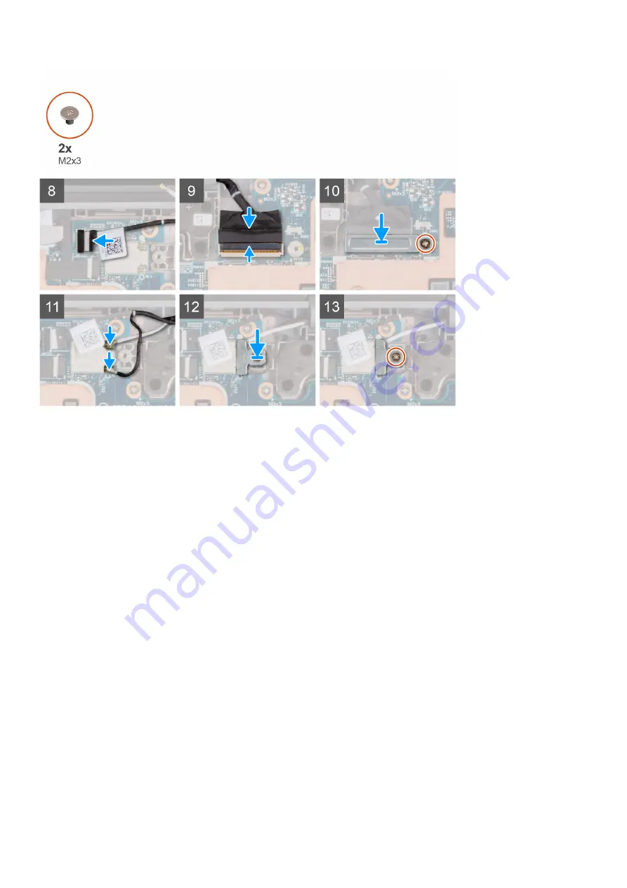
13. Connect the display cable to its connector on the system board. Close the latch to secure the cable.
14. Replace the display cable bracket on the system board. Replace the singe screw (M2x3) to secure the display bracket to the

system board.

15. Connect the two antenna cables to the WLAN module on the system board.
16. Replace the WLAN antenna cable bracket on the system board.
17. Replace the singe screw (M2x3) to secure the WLAN antenna cable bracket to the system board.

Next steps

1. For systems shipped with a world-facing camera, install the 

world-facing camera

.

2. Install the 

heatsink assembly

.

3. For systems that are shipped with a Solid State Drive (SSD), install the 

solid-state drive

.

Removing and installing components

45

Содержание Latitude 3120

Страница 1: ...Latitude 3120 Service Manual Regulatory Model P32T P33T Regulatory Type P32T001 P33T001 April 2021 Rev A01 ...

Страница 2: ...ential damage to hardware or loss of data and tells you how to avoid the problem WARNING A WARNING indicates a potential for property damage personal injury or death 2021 Dell Inc or its subsidiaries All rights reserved Dell EMC and other trademarks are trademarks of Dell Inc or its subsidiaries Other trademarks may be trademarks of their respective owners ...

Страница 3: ...kers 19 Removing the speakers 19 Installing the speaker 20 Coin cell battery 21 Removing the coin cell battery 21 Installing the coin cell battery 22 Audio board 23 Removing the audio board 23 Installing the audio board 24 Battery 25 Lithium ion battery precautions 25 Removing the 3 cell battery 25 Installing the 3 cell battery 26 Removing the 4 cell battery 27 Installing the 4 cell battery 28 Dis...

Страница 4: ...ving the front facing camera 56 Installing the front facing camera 57 Display cable 58 Removing the display cable 58 Installing the display cable 59 Display hinges 60 Removing the display hinge 60 Installing the display hinge 61 Display back cover assembly 63 Display back cover assembly 63 Base cover assembly 64 Replacing the base cover assembly 64 Chapter 3 Drivers and downloads 66 Chapter 4 Syst...

Страница 5: ...roubleshooting 81 Built in self test BIST 81 LCD Built in Self Test BIST 81 Dell SupportAssist Pre boot System Performance Check diagnostics 82 Running the SupportAssist Pre Boot System Performance Check 82 Diagnostic LED behavior 82 Diagnostic error messages 84 System error messages 87 Recovering the operating system 87 Real Time Clock RTC Reset 88 Flashing the BIOS 88 Backup media and recovery o...

Страница 6: ...the same time as touching a connector on the back of the computer CAUTION Handle components and cards with care Do not touch the components or contacts on a card Hold a card by its edges or by its metal mounting bracket Hold a component such as a processor by its edges not by its pins CAUTION When you disconnect a cable pull on its connector or on its pull tab not on the cable itself Some cables h...

Страница 7: ...ablets notebooks Bonding Bonding is a method for connecting two or more grounding conductors to the same electrical potential This is done through the use of a field service electrostatic discharge ESD kit When connecting a bonding wire ensure that it is connected to bare metal and never to a painted or non metal surface The wrist strap should be secure and in full contact with your skin and ensur...

Страница 8: ... a wrist strap tester in order to avoid accidental ESD hardware damage It is recommended to test the wrist strap and bonding wire at least once per week ESD Wrist Strap Tester The wires inside of an ESD strap are prone to damage over time When using an unmonitored kit it is a best practice to regularly test the strap prior to each service call and at a minimum test once per week A wrist strap test...

Страница 9: ...ensitive components After working inside your computer About this task CAUTION Leaving stray or loose screws inside your computer may severely damage your computer Steps 1 Replace all screws and ensure that no stray screws remain inside your computer 2 Connect any external devices peripherals or cables you removed before working on your computer 3 Replace any media cards discs or any other parts t...

Страница 10: ...ommended for field technicians NOTE The 0 screw driver is for screws 0 1 and the 1 screw driver is for screws 2 4 Screw List The following table shows the screw list and the image of the screws Table 1 Screw list Component Screw type Quantity Image 3 cell battery M2x3 4 Dummy battery cell M2x3 2 4 cell battery M2x3 5 Audio board cable M2x3 2 Heatsink assembly M2x3 4 World facing camera M2 5x2 5 1 ...

Страница 11: ... Display hinge bracket M2 5x5 6 N lock M2x4 1 display hinge bracket Latitude 3120 M2 5x2 5 M2x2 5 4 2 Display panel Latitude 3120 M2x2 5 4 Display bezel Latitude 3120 M2 5x3 8 4 System board with USB Type C port System board without USB Type C port M2x5 M2x5 4 6 USB Type C bracket M2x4 3 USB Type A bracket M2x3 5 2 Base cover Captive screws 9 Removing and installing components 11 ...

Страница 12: ...Major components of your system 1 Display assembly 12 Removing and installing components ...

Страница 13: ...bers for the original system configuration purchased These parts are available according to warranty coverages purchased by the customer Contact your Dell sales representative for purchase options Palmrest and Keyboard assembly Removing the palmrest and keyboard Prerequisites Follow the procedure in before working inside your computer About this task The following images indicate the location of t...

Страница 14: ...14 Removing and installing components ...

Страница 15: ...computer chassis CAUTION Do not open the palmrest assembly more than 60 degrees as it may damage the keyboard Flexible Printed Circuits FPC and touchpad Flexible Flat Cable FFC 6 Gently flip over the palmrest assembly with the keyboard facing downward CAUTION Do not apply excess force to the palmrest assembly while flipping it over as it may damage to the keyboard FPC and touchpad FFC 7 Disconnect...

Страница 16: ...16 Removing and installing components ...

Страница 17: ... place 4 Replace the nine captive screws that secure the palmrest assembly to the computer chassis Next steps Follow the procedure in after working inside your computer Solid state drive Removing the solid state drive Prerequisites 1 Follow the procedure in before working inside your computer 2 Remove the palmrest and keyboard assembly About this task NOTE The following steps are for the systems t...

Страница 18: ...the M 2 card slot on the system board Installing the solid state drive Prerequisites If you are replacing a component remove the existing component before performing the installation procedure About this task NOTE The following steps are for the systems that are shipped with an M 2 solid state drive SSD The following image indicates the location of the SSD and provides a visual representation of t...

Страница 19: ...lot on system board Next steps 1 Install the palmrest and keyboard assembly 2 Follow the procedure in after working inside your computer Speakers Removing the speakers Prerequisites 1 Follow the procedure in before working inside your computer 2 Remove the palmrest and keyboard assembly About this task The following image indicates the location of the speakers and provides a visual representation ...

Страница 20: ...hannel 4 Lift and remove the speakers from their slots on the computer chassis Installing the speaker Prerequisites If you are replacing a component remove the existing component before performing the installation procedure About this task The following image indicates the location of the speaker and provides a visual representation of the installation procedure 20 Removing and installing componen...

Страница 21: ...r cable on the system board 4 Connect the speaker cable to the connector on the system board Next steps 1 Install the palmrest and keyboard assembly 2 Follow the procedure in after working inside your computer Coin cell battery Removing the coin cell battery Prerequisites 1 Follow the procedure in before working inside your computer 2 Remove the palmrest and keyboard assembly Removing and installi...

Страница 22: ...ift and remove it from the computer chassis Installing the coin cell battery Prerequisites If you are replacing a component remove the existing component before performing the installation procedure About this task If you are replacing a component remove the existing component before performing the installation procedure The following image indicates the location of the coin cell battery and provi...

Страница 23: ...low the procedure in after working inside your computer Audio board Removing the audio board Prerequisites 1 Follow the procedure in before working inside your computer 2 Remove the palmrest and keyboard assembly 3 Remove the speakers About this task The following image indicates the location of the audio board and provides a visual representation of the removal procedure Removing and installing c...

Страница 24: ...ove the audio board from the computer chassis Installing the audio board Prerequisites If you are replacing a component remove the existing component before performing the installation procedure About this task The following image indicates the location of the audio board and provides a visual representation of the installation procedure 24 Removing and installing components ...

Страница 25: ...y Do not use tools of any kind to pry on or against the battery Ensure any screws during the servicing of this product are not lost or misplaced to prevent accidental puncture or damage to the battery and other system components If the battery gets stuck inside your computer as a result of swelling do not try to release it as puncturing bending or crushing a lithium ion battery can be dangerous In...

Страница 26: ...the 3 cell battery Prerequisites If you are replacing a component remove the existing component before performing the installation procedure About this task NOTE The following steps are for the systems that are shipped with a 3 cell battery NOTE If the battery is disconnected from system board there is delay during computer boot as the computer undergoes Real Time Clock RTC reset NOTE The double s...

Страница 27: ...re in after working inside your computer Removing the 4 cell battery Prerequisites 1 Follow the procedure in before working inside your computer 2 Remove the palmrest and keyboard assembly NOTE The following steps are for the systems that are shipped with a 4 cell battery NOTE If the battery is disconnected from system board there is delay during computer boot as the computer undergoes Real Time C...

Страница 28: ...the 4 cell battery Prerequisites If you are replacing a component remove the existing component before performing the installation procedure About this task NOTE The following steps are for the systems that are shipped with a 4 cell battery NOTE If the battery is disconnected from system board there is delay during computer boot as the computer undergoes Real Time Clock RTC reset NOTE The double s...

Страница 29: ...ace 5 Connect the battery cable to the system board Next steps 1 Install the palmrest and keyboard assembly 2 Follow the procedure in after working inside your computer Display assembly Removing the display assembly Prerequisites 1 Follow the procedure in before working inside your computer 2 Remove the palmrest and keyboard assembly About this task The following images indicate the location of th...

Страница 30: ...30 Removing and installing components ...

Страница 31: ...m the connector on the system board 6 For 2 in 1 systems disconnect the touch cable from the connector on the system board 7 Open the system to 120 degrees 8 Remove the single M2x4 screw and six M2 5x5 screws that secure the display assembly to the computer chassis 9 Lift and remove the display assembly from the computer chassis Installing the display assembly Prerequisites If you are replacing a ...

Страница 32: ...32 Removing and installing components ...

Страница 33: ...e the singe screw M2x3 to secure the display bracket to the system board 6 Connect the two antenna cables to the WLAN module on the system board 7 Replace the WLAN antenna cable bracket on the system board 8 Replace the singe screw M2x3 that secures the WLAN antenna cable bracket to the system board Next steps 1 Install the palmrest and keyboard assembly 2 Follow the procedure in after working ins...

Страница 34: ...the power adapter port to the computer chassis 3 Lift and remove the power adapter port from the computer chassis Installing the power adapter port Prerequisites If you are replacing a component remove the existing component before performing the installation procedure About this task The following image indicates the location of the power adapter port and provides a visual representation of the i...

Страница 35: ...ng inside your computer World facing camera Removing the world facing camera Prerequisites NOTE The following world facing camera removal procedure is applicable for Latitude 3120 2 in 1 only CAUTION This is a fragile component Handle with care 1 Follow the procedure in before working inside your computer 2 Remove the palmrest and keyboard assembly About this task The following images indicate the...

Страница 36: ... and remove the world facing camera module from the computer chassis Installing the world facing camera Prerequisites NOTE The following world facing camera installing procedure is applicable for Latitude 3120 2 in 1 only CAUTION This is a fragile component Handle with care About this task The following image indicates the location of the front facing camera and provides a visual representation of...

Страница 37: ...xt steps 1 Install the palmrest and keyboard assembly 2 Follow the procedure in after working inside your computer Heatsink assembly Removing the heatsink assembly Prerequisites 1 Follow the procedure in before working inside your computer 2 Remove the palmrest and keyboard assembly About this task The following images indicate the location of the heatsink assembly and provide a visual representat...

Страница 38: ...embly to the system board 3 Lift and remove the heatsink assembly from the system board Installing the heatsink assembly Prerequisites If you are replacing a component remove the existing component before performing the installation procedure About this task The following image indicates the location of the heatsink assembly and provides a visual representation of the installation procedure 38 Rem...

Страница 39: ...replace the single screw M2x3 that secures the SSD thermal plate to the system board Next steps 1 Install the palmrest and keyboard assembly 2 Follow the procedure in after working inside your computer Dummy battery cell Removing the dummy battery cell Prerequisites 1 Follow the procedure in before working inside your computer 2 Remove the palmrest and keyboard assembly Removing and installing com...

Страница 40: ...tery cell to the system board 3 Disconnect the battery cable from the system board 4 Lift and remove the dummy battery cell from the computer chassis Installing the dummy battery cell Prerequisites If you are replacing a component remove the existing component before performing the installation procedure About this task NOTE The following steps are for the systems that are shipped with a 3 cell ba...

Страница 41: ... after working inside your computer System board Removing the system board Prerequisites 1 Follow the procedure in before working inside your computer 2 Remove the palmrest and keyboard assembly 3 For systems that are shipped with a Solid State Drive SSD remove the solid state drive 4 Remove the heatsink assembly 5 For systems shipped with a world facing camera remove the world facing camera About...

Страница 42: ...42 Removing and installing components ...

Страница 43: ...d 10 For systems that are shipped with a USB Type C port lift and remove the USB Type C bracket from the system board 11 Remove the two screws M2x3 that secure the USB Type A bracket to the system board 12 Lift and remove the USB Type A bracket from the system board 13 For systems that are shipped with a USB Type C port remove the four screws M2x3 that secure the system board to the computer chass...

Страница 44: ...44 Removing and installing components ...

Страница 45: ...e USB Type C bracket to the system board 10 Connect the speaker cable and the audio board cable to their connectors on the system board 11 Connect the power adapter port cable to its connector on the system board 12 For 2 in 1 systems connect the touch cable to the connector on the system board 13 Connect the display cable to its connector on the system board Close the latch to secure the cable 14...

Страница 46: ...tes 1 Follow the procedure in before working inside your computer 2 Remove the palmrest and keyboard assembly 3 Remove the display assembly About this task NOTE The following steps are for 2 in 1 systems The following images indicate the location of the touch panel assembly and provide a visual representation of the removal procedure 46 Removing and installing components ...

Страница 47: ...n the surface 6 Lift and remove the touch panel assembly from the display cover 7 Gently flip over the display panel assembly and place it on a flat surface CAUTION The display cable is not long enough to completely flatten the panel Technicians must move the touch panel assembly underneath the display hinges 8 Peel off the mylar tape that secures the display cable on the rear of the display panel...

Страница 48: ...ting component before performing the installation procedure About this task NOTE The following steps are for 2 in 1 systems The following image indicates the location of the touch panel assembly and provides a visual representation of the installation procedure 48 Removing and installing components ...

Страница 49: ... Gently snap the touch panel assembly into place Next steps 1 Install the display assembly 2 Install the palmrest and keyboard assembly 3 Follow the procedure in after working inside your computer Display bezel Removing the display bezel Prerequisites NOTE The following steps are for Latitude 3120 systems 1 Follow the procedure in before working inside your computer 2 Remove the palmrest and keybo...

Страница 50: ...50 Removing and installing components ...

Страница 51: ...splay bezel 3 Use the scribe to pry open the top left and right sides of the display bezel 4 Lift and remove the display bezel from the display assembly Installing the display bezel Prerequisites If you are replacing a component remove the existing component before performing the installation procedure About this task NOTE The following steps are for Latitude 3120 systems The following images indi...

Страница 52: ...eplace the four screws M2 5x3 8 to secure the display bezel on the display assembly Next steps 1 Install the display assembly 2 Install the palmrest and keyboard assembly 3 Follow the procedure in after working inside your computer Display panel Removing the display panel Prerequisites NOTE The following steps are for Latitude 3120 systems 1 Follow the procedure in before working inside your compu...

Страница 53: ...Remove the display bezel About this task The following images indicate the location of the display panel and provide a visual representation of the removal procedure Removing and installing components 53 ...

Страница 54: ...splay cable from the connector on the display panel 6 Lift and remove the display panel from the display assembly Installing the display panel Prerequisites If you are replacing a component remove the existing component before performing the installation procedure About this task NOTE The following steps are for Latitude 3120 systems The following images indicate the location of the display panel ...

Страница 55: ...Removing and installing components 55 ...

Страница 56: ...5 Replace the four screws M2x2 5 to secure the display panel on the display assembly 6 Gently flip over the display panel Next steps 1 Install the display bezel 2 Install the display assembly 3 Install the palmrest and keyboard assembly 4 Follow the procedure in after working inside your computer Front facing camera Removing the front facing camera Prerequisites 1 Follow the procedure in before wo...

Страница 57: ... display cable from the front facing camera module 3 Use a plastic scribe to pry the front facing camera module from the display cover 4 Lift and remove the front facing camera module from the display cover Installing the front facing camera Prerequisites If you are replacing a component remove the existing component before performing the installation procedure About this task The following image ...

Страница 58: ...y 4 Install the palmrest and keyboard assembly 5 Follow the procedure in after working inside your computer Display cable Removing the display cable Prerequisites 1 Follow the procedure in before working inside your computer 2 Remove the palmrest and keyboard assembly 3 Remove the display assembly 4 Remove the display bezel 5 Remove the display panel About this task The following image indicates t...

Страница 59: ...e from the routing channel on the bottom left side of the display cover 5 Peel off the display cable from the display cover Installing the display cable Prerequisites If you are replacing a component remove the existing component before performing the installation procedure About this task The following image indicates the location of the display cable and provides a visual representation of the i...

Страница 60: ...e 5 Affix the tape to secure the display connector on the front facing camera module Next steps 1 Install the display panel 2 Install the display bezel 3 Install the display assembly 4 Install the palmrest and keyboard assembly 5 Follow the procedure in after working inside your computer Display hinges Removing the display hinge Prerequisites 1 Follow the procedure in before working inside your co...

Страница 61: ...LAN antenna cables 3 For Latitude 3120 remove the two M2x2 5 screws and four M2 5x2 5 screws that secure the display hinges to the display assembly 4 For Latitude 3120 2 in 1 remove the six M2 5x2 5 screws and four M2x2 screws that secure the display hinges to the display assembly 5 Open the display hinges to 45 degrees 6 Remove the display hinges from the display assembly Installing the display h...

Страница 62: ...isplay assembly 3 For Latitude 3120 2 in 1 replace the six M2 5x2 5 screws and four M2x2 screws to secure the display hinges to the display assembly 4 Affix the tape from the left hinge to secure the display cable 5 Affix the tape from the right hinge to secure the WLAN antenna cables Next steps 1 Install the palmrest and keyboard assembly 2 Install the display assembly 3 Install the display bezel...

Страница 63: ...assembly 3 Remove the display assembly 4 Remove the display bezel 5 Remove the display panel 6 For 2 in 1 systems remove the touch panel assembly 7 Remove the front facing camera 8 Remove the display cable 9 Remove the display hinges About this task After performing the preceding steps you are left with the display cover assembly Removing and installing components 63 ...

Страница 64: ...Remove the palmrest and keyboard assembly 3 For systems that are shipped with a Solid State Drive SSD remove the solid state drive 4 Remove the speakers 5 Remove the audio board 6 Remove the 3 cell battery or the 4 cell battery depending on the system configuration 7 Remove the display assembly 8 Remove the power adapter port 9 For systems shipped with a world facing camera remove the world facing...

Страница 65: ...5 Install the power adapter port 6 Install the display assembly 7 Install the 3 cell battery or the4 cell battery depending on the system configuration 8 Install the audio board 9 Install the speakers 10 For systems that are shipped with a Solid State Drive SSD install the solid state drive 11 Install the palmrest and keyboard assembly 12 Follow the procedure in after working inside your computer ...

Страница 66: ...ort enter the Service Tag of your notebook and then click Submit NOTE If you do not have the Service Tag use the auto detect feature or manually browse for your notebook model 4 Click Drivers and Downloads 5 Select the operating system installed on your notebook 6 Scroll down the page and select the driver to install 7 Click Download File to download the driver for your notebook 8 After the downlo...

Страница 67: ...in the system This menu is useful when you are attempting to boot to a particular device or to bring up the diagnostics for the system Using the boot menu do not change the boot order that is stored in the BIOS The options are Legacy External Device Boot Onboard NIC UEFI Boot UEFI TOSHIBA MQ01ACF050 Other Options BIOS Setup Device Configuration BIOS Flash Update Diagnostics Intel R Management Engi...

Страница 68: ...wnership Date and Express Service Code Signed Firmware Update is enabled Memory Information Displays Memory Installed Memory Available Memory Speed Memory Channel Mode and Memory Technology NOTE Due to an amount of memory being assigned for system use Memory Available is less than Memory Installed NOTE Certain operating systems may not be able to use all the available memory Processor Information ...

Страница 69: ...e Fastboot option is set to Minimal the Enable USB Boot Support setting is ignored and the system will not boot from any Pre boot USB devices Enable External USB Port enabled by default NOTE A USB keyboard and mouse connected to the platform s USB ports will continue to function within the BIOS Setup if this option is disabled USB PowerShare This option configures the USB PowerShare feature behavi...

Страница 70: ...et The admin password must be set first if an admin password is used with a system password and or HDD password System Password Allows you to set change and delete the system password Password Configuration Allows you to control the rules when setting a password The value of characters cannot be less than 4 Lower Caste Letter Upper Case Letter Digit Special Character All options are disabled by de...

Страница 71: ...from Absolute Software Enabled enabled by default Enable the Absolute Persistence and load the firmware Persistence Module Disabled Disable Absolute Persistence The firmware Persistence Module is not installed Permanently Disabled Permanently disables Absolute Persistence module interface from farther use WARNING The Permanently Disabled option can only be selected once When Permanently Disabled i...

Страница 72: ...he Intel SpeedStep mode of the processor The Enable Intel SpeedStep option is enabled by default If the option is disabled it places the processor into the highest performance state and prevents the Intel SpeedStep applet or native operating system driver from adjusting the processor s performance If the option is enabled it allows the Intel SpeedStep enabled CPU to operate in multiple performance...

Страница 73: ... S3 NOTE This feature is only functional when the AC power adapter is connected If the AC power adapter is removed during Standby the system setup removes power from all the USB ports to conserve battery power Wake on Dell USB C Dock enabled by default allows the system to automatically wake up when connecting to a Dell USB C dock Enable USB Wake Support disabled by default Wireless Radio Control ...

Страница 74: ...ndard Charge is used for maximum battery health Setting Work Period to zero disables this feature for that day The Enable Advanced Battery Charge Mode option is disabled by default Primary Battery Charge Configuration Allows you to select the charging mode for the battery The options are Adaptive enabled by default battery settings are adaptively optimized based on your typical battery usage patte...

Страница 75: ...dary The F1 F2 keys control the secondary functions Fn is required to access the standard functions disabled by default Fastboot Allows you to speed up the boot process by bypassing some of the compatibility steps The options are Minimal reduces boot time by skipping certain hardware and configuration initialization during boot enabled by default Thorough performs complete hardware and configurati...

Страница 76: ...g the additional hardware capabilities provided by Intel Virtualization technology for direct I O NOTE Trusted Execution requires VT for Direct I O to be enabled The Enable VT for Direct I O option is enabled by default Wireless Table 11 Wireless Option Description Wireless Device Enable Allows you to enable or disable the internal wireless devices WLAN Bluetooth All the options are enabled by def...

Страница 77: ... available for Self encrypting drives SED System logs Table 13 System logs Option Description BIOS Events Allows you to view and clear the System Setup BIOS POST events Thermal and Self Test Events Allows you to view and clear the System Setup Thermal events Power Events Allows you to view and clear the System Setup Power events SupportAssist System Resolution Table 14 SupportAssist System Resolut...

Страница 78: ...for only THIS PC XXXXXXX NOTE XXXXXXX denotes the Service Tag 9 Select the latest BIOS file and click Download 10 After the download is complete browse to the folder where you saved the system BIOS executable file 11 Double click the system BIOS executable file NOTE Follow the on screen instructions Updating BIOS on systems with BitLocker enabled CAUTION If BitLocker is not suspended before updati...

Страница 79: ... Password type Description System password Password that you must enter to log on to your system Setup password Password that you must enter to access and make changes to the BIOS settings of your computer You can create a system password and a setup password to secure your computer CAUTION The password features provide a basic level of security for the data on your computer CAUTION Anyone can acc...

Страница 80: ...ed in the System Setup before attempting to delete or change the existing System and Setup password You cannot delete or change an existing System or Setup password if the Password Status is Locked About this task To enter the System Setup press F2 immediately after a power on or reboot Steps 1 In the System BIOS or System Setup screen select System Security and press Enter The System Security scr...

Страница 81: ...olid Amber Battery LED error code of 2 8 blinks Amber x2 then pause then blinks White x8 Repair instruction Indicates a problem with the system board Indicates a problem with the system board LCD Built in Self Test BIST Dell laptops have a built in diagnostic tool that helps you determine if the screen abnormality you are experiencing is an inherent problem with the LCD screen of the Dell laptop o...

Страница 82: ... ensure that you are present at the computer terminal when the diagnostic tests are performed For more information see Resolve Hardware Issues With Built in and Online Diagnostics SupportAssist ePSA ePSA or PSA Error Codes Running the SupportAssist Pre Boot System Performance Check Steps 1 Turn on your computer 2 As the computer boots press the F12 key as the Dell logo appears 3 On the boot menu s...

Страница 83: ...ory modules among the slots If problem persists replace the memory module 2 5 Invalid memory installed Reset and swap memory modules among the slots If problem persists replace the memory module 2 6 System board Chipset Error Replace the system board 2 7 LCD failure SBIOS message Replace the LCD module 2 8 LCD failure EC detection of power rail failure Replace the system board 3 1 CMOS battery fai...

Страница 84: ...xternal mouse check the cable connection Enable the Pointing Device option in the System Setup program BAD COMMAND OR FILE NAME Ensure that you have spelled the command correctly put spaces in the proper place and used the correct path name CACHE DISABLED DUE TO FAILURE The primary cache internal to the microprocessor has failed Contact Dell CD DRIVE CONTROLLER FAILURE The optical drive does not r...

Страница 85: ...not respond to commands from the computer Shut down the computer remove the hard drive and boot the computer from an optical drive Then shut down the computer reinstall the hard drive and restart the computer If the problem persists try another drive Run the Hard Disk Drive tests in Dell Diagnostics HARD DISK DRIVE READ FAILURE The hard drive may be defective Shut down the computer remove the hard...

Страница 86: ...TOR ON HARD DRIVE The operating system may be corrupted Contact Dell NO TIMER TICK INTERRUPT A chip on the system board may be malfunctioning Run the System Set tests in Dell Diagnostics NOT ENOUGH MEMORY OR RESOURCES EXIT SOME PROGRAMS AND TRY AGAIN You have too many programs open Close all windows and open the program that you want to use OPERATING SYSTEM NOT FOUND Reinstall the operating system...

Страница 87: ... RTC is reset BIOS Setup default has been loaded CPU fan failure CPU fan has failed System fan failure System fan has failed Hard disk drive failure Possible hard disk drive failure during POST Keyboard failure Keyboard failure or loose cable If reseating the cable does not solve the problem replace the keyboard No boot device available No bootable partition on hard disk drive the hard disk drive ...

Страница 88: ...lash update the BIOS when an update is available or when you replace the system board Follow these steps to flash the BIOS Steps 1 Turn on your computer 2 Go to www dell com support 3 Click Product support enter the Service Tag of your computer and then click Search NOTE If you do not have the Service Tag use the product ID or manually browse for your computer model 4 Click Drivers downloads Find ...

Страница 89: ...tatic electricity that remains on the computer even after it has been powered off and the battery has been removed The following procedure provides the instructions on how to conduct flea power release Steps 1 Turn off your computer 2 Disconnect the power adapter from your computer 3 Press and hold the power button for 15 seconds to drain the flea power 4 Connect the power adapter to your computer...

Страница 90: ...r Express Service Code at www dell com support For more information on how to find the Service Tag for your computer see Locate the Service Tag on your computer Dell knowledge base articles for a variety of computer concerns 1 Go to www dell com support 2 On the menu bar at the top of the Support page select Support Knowledge Base 3 In the Search field on the Knowledge Base page type the keyword t...

Отзывы: