background image

ESD Wrist Strap Tester

 – The wires inside of an ESD strap are prone to damage over time. When using an unmonitored

kit, it is a best practice to regularly test the strap prior to each service call, and at a minimum, test once per week. A
wrist strap tester is the best method for doing this test. If you do not have your own wrist strap tester, check with your
regional office to find out if they have one. To perform the test, plug the wrist-strap's bonding-wire into the tester while it is
strapped to your wrist and push the button to test. A green LED is lit if the test is successful; a red LED is lit and an alarm
sounds if the test fails.

Insulator Elements 

– It is critical to keep ESD sensitive devices, such as plastic heat sink casings, away from internal parts

that are insulators and often highly charged.

Working Environment 

– Before deploying the ESD Field Service kit, assess the situation at the customer location. For

example, deploying the kit for a server environment is different than for a desktop or portable environment. Servers are
typically installed in a rack within a data center; desktops or portables are typically placed on office desks or cubicles. Always
look for a large open flat work area that is free of clutter and large enough to deploy the ESD kit with additional space to
accommodate the type of system that is being repaired. The workspace should also be free of insulators that can cause an
ESD event. On the work area, insulators such as Styrofoam and other plastics should always be moved at least 12 inches or
30 centimeters away from sensitive parts before physically handling any hardware components

ESD Packaging 

– All ESD-sensitive devices must be shipped and received in static-safe packaging. Metal, static-shielded

bags are preferred. However, you should always return the damaged part using the same ESD bag and packaging that the
new part arrived in. The ESD bag should be folded over and taped shut and all the same foam packing material should be
used in the original box that the new part arrived in. ESD-sensitive devices should be removed from packaging only at an
ESD-protected work surface, and parts should never be placed on top of the ESD bag because only the inside of the bag is
shielded. Always place parts in your hand, on the ESD mat, in the system, or inside an anti-static bag.

Transporting Sensitive Components

 – When transporting ESD sensitive components such as replacement parts or parts

to be returned to Dell, it is critical to place these parts in anti-static bags for safe transport.

ESD protection summary

It is recommended that all field service technicians use the traditional wired ESD grounding wrist strap and protective anti-static
mat at all times when servicing Dell products. In addition, it is critical that technicians keep sensitive parts separate from all
insulator parts while performing service and that they use anti-static bags for transporting sensitive components.

Transporting sensitive components

When transporting ESD sensitive components such as replacement parts or parts to be returned to Dell, it is critical to place
these parts in anti-static bags for safe transport.

After working inside your computer

About this task

NOTE:

 Leaving stray or loose screws inside your computer may severely damage your computer.

Steps

1. Replace all screws and ensure that no stray screws remain inside your computer.
2. Connect any external devices, peripherals, or cables you removed before working on your computer.
3. Replace any media cards, discs, or any other parts that you removed before working on your computer.
4. Connect your computer and all attached devices to their electrical outlets.
5. Turn on your computer.

10

Working inside your computer

Содержание Inspiron 3420

Страница 1: ...Latitude 3420 Service Manual for computers with integrated graphics Regulatory Model P144G Regulatory Type P144G001 P144G002 July 2021 Rev A01 ...

Страница 2: ...ential damage to hardware or loss of data and tells you how to avoid the problem WARNING A WARNING indicates a potential for property damage personal injury or death 2021 Dell Inc or its subsidiaries All rights reserved Dell EMC and other trademarks are trademarks of Dell Inc or its subsidiaries Other trademarks may be trademarks of their respective owners ...

Страница 3: ...cover 17 Installing the base cover 19 Battery cable 20 Lithium ion battery precautions 20 Removing the battery cable 21 Installing the battery cable 22 Memory module 22 Removing the memory module 22 Installing the memory module 23 M 2 solid state drive 25 Removing the M 2 2230 solid state drive 25 Installing the M 2 2230 solid state drive 25 Removing the M 2 2280 solid state drive 26 Installing th...

Страница 4: ...e display panel 54 Installing the display panel 57 Display bezel 60 Removing the display bezel 60 Installing the display bezel 61 Heatsink assembly 62 Removing the heatsink assembly 62 Installing the heatsink assembly 62 Power adapter port 63 Removing the power adapter port 63 Installing the power adapter port 64 Coin cell battery 65 Removing the coin cell battery 65 Installing the coin cell batte...

Страница 5: ...lling the display back cover 95 Chapter 3 Drivers and downloads 97 Chapter 4 BIOS setup 98 BIOS overview 98 Entering BIOS setup program 98 Navigation keys 98 One time boot menu 99 System setup options 99 Updating the BIOS 109 Updating the BIOS in Windows 109 Updating the BIOS in Linux and Ubuntu 109 Updating the BIOS using the USB drive in Windows 109 Updating the BIOS from the F12 One Time boot m...

Страница 6: ...in Self Test BIST 115 System diagnostic lights 115 Recovering the operating system 117 Real Time Clock RTC Reset 117 Backup media and recovery options 117 WiFi power cycle 118 Drain residual flea power perform hard reset 118 Chapter 6 Getting help and contacting Dell 119 6 Contents ...

Страница 7: ...tor on the back of the computer CAUTION Handle components and cards with care Do not touch the components or contacts on a card Hold a card by its edges or by its metal mounting bracket Hold a component such as a processor by its edges not by its pins CAUTION When you disconnect a cable pull on its connector or on its pull tab not on the cable itself Some cables have connectors with locking tabs i...

Страница 8: ...mputer shuts down you may perform the replacement procedures without disconnecting the battery cable from the system board Exiting Service Mode Service Mode allows users to immediately cut off electricity from the computer and conduct repairs without disconnecting the battery cable from the system board To exit Service Mode 1 Connect the AC adapter to the power adapter port on your computer 2 Pres...

Страница 9: ...mittent memory errors etc Perform the following steps to prevent ESD damage Use a wired ESD wrist strap that is properly grounded The use of wireless anti static straps is no longer allowed they do not provide adequate protection Touching the chassis before handling parts does not ensure adequate ESD protection on parts with increased sensitivity to ESD damage Handle all static sensitive component...

Страница 10: ...are preferred However you should always return the damaged part using the same ESD bag and packaging that the new part arrived in The ESD bag should be folded over and taped shut and all the same foam packing material should be used in the original box that the new part arrived in ESD sensitive devices should be removed from packaging only at an ESD protected work surface and parts should never be...

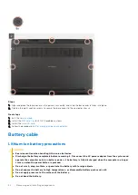
Страница 11: ...The following table shows the screw list and the image of the screws Table 1 Screw list Component Screw type Quantity Image Base cover Captive screws 8 M 2 Solid state drive bracket M2x3 1 M 2 Solid state drive conversion bracket M2x3 1 M 2 Solid state drive conversion plate M2x3 2 Hard disk drive module M2X4 5 3 Hard disk drive M3x3 4 WLAN card M2x3 1 WWAN card M2x3 1 System Fan M2x3 2 3 cell bat...

Страница 12: ...6 2 Heatsink assembly Captive screws 7 For systems enabled with discrete graphic card 4 For systems enabled with integrated graphic card Power adapter port M2x3 1 Ethernet port M2x5 1 I O board M2x3 2 System board M2x2 2 Touchpad bracket M2x2 5 3 Touchpad module M2x2 4 WWAN I O board M2x3 2 12 Removing and installing components ...

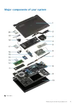
Страница 13: ...Major components of your system 1 Base cover Removing and installing components 13 ...

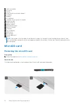
Страница 14: ...pter port 20 WLAN NOTE Dell provides a list of components and their part numbers for the original system configuration purchased These parts are available according to warranty coverages purchased by the customer Contact your Dell sales representative for purchase options MicroSD card Removing the microSD card Prerequisites 1 Follow the procedure in before working inside your computer About this t...

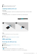
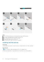
Страница 15: ... card installation procedure Steps Insert the microSD card into its slot until it clicks into place Next steps 1 Follow the procedure in after working inside your computer SIM card tray Removing the SIM card tray Prerequisites 1 Follow the procedure in before working inside your computer 2 Remove the microSD card About this task NOTE The following steps are applicable only for 4G LTE enabled syste...

Страница 16: ...from the SIM tray 5 Slide the SIM card tray back into the slot on the computer Installing the SIM card tray Prerequisites If you are replacing a component remove the necessary component before the installation procedure About this task NOTE The following steps are applicable only for 4G LTE enabled systems The following image provides a visual representation of the SIM card tray installation proce...

Страница 17: ...the dedicated slot on the SIM card tray 5 Slide the SIM card tray back into the slot on the computer Next steps 1 Install the microSD card 2 Follow the procedure in after working inside your computer Base cover Removing the base cover Prerequisites 1 Follow the procedure in before working inside your computer 2 Remove the microSD card 3 Remove the SIM card tray for 4G LTE enabled systems 4 Enter t...

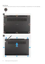
Страница 18: ...About this task The following images indicate the location of the base cover and provide a visual representation of the removal procedure 18 Removing and installing components ...

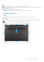
Страница 19: ...y lift and remove the base cover from the chassis NOTE Be careful of the latches while removing the base cover as the latches may break Installing the base cover Prerequisites If you are replacing a component remove the existing component before performing the installation procedure About this task The following images indicate the location of the battery and provide a visual representation of the...

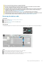
Страница 20: ...ery precautions CAUTION Exercise caution when handling Lithium ion batteries Discharge the battery completely before removing it Disconnect the AC power adapter from the system and operate the computer solely on battery power the battery is fully discharged when the computer no longer turns on when the power button is pressed Do not crush drop mutilate or penetrate the battery with foreign objects...

Страница 21: ... be replaced and disposed properly For guidelines on how to handle and replace swollen Lithium ion batteries see Handling swollen Lithium ion batteries Removing the battery cable Prerequisites 1 Follow the procedure in before working inside your computer 2 Remove the microSD card 3 Remove the SIM card tray for 4G LTE enabled systems 4 Remove the base cover About this task The following image indic...

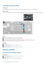
Страница 22: ...r on the battery to lock 3 Route the battery cable through the routing channel in the battery and adhere the adhesive tapes 4 Connect the battery cable to the connector on the system board Next steps 1 Install the base cover 2 Install the SIM card tray for 4G LTE enabled systems 3 Install the microSD card 4 Follow the procedure in after working inside your computer Memory module Removing the memor...

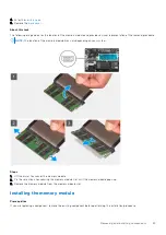
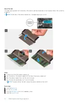
Страница 23: ...odule may vary depending on your system Steps 1 Lift the mylar to uncover the memory module 2 Pry the retention clips securing the memory module slot until the memory module pops up 3 Remove the memory module from the memory module slot Installing the memory module Prerequisites If you are replacing a component remove the existing component before performing the installation procedure Removing and...

Страница 24: ... module slot 2 Align the notch on the memory module with the tab on the memory module slot 3 Slide the memory module firmly into the slot at an angle 4 Press the memory module down until it clicks into place NOTE If you do not hear the click remove the memory module and reinstall it Next steps 1 Install the base cover 2 Exit the service mode 3 Install the SIM card tray for 4G LTE enabled systems 4...

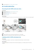
Страница 25: ...tate drive and provides a visual representation of the removal procedure Steps 1 Remove the M2x3 screw that secures the solid state drive to the system board 2 Slide and remove the solid state drive from the solid state drive slot on the system board Installing the M 2 2230 solid state drive Prerequisites If you are replacing a component remove the existing component before performing the installa...

Страница 26: ...or 4G LTE enabled systems 4 Install the microSD card 5 Follow the procedure in after working inside your computer Removing the M 2 2280 solid state drive Prerequisites 1 Follow the procedure in before working inside your computer 2 Remove the microSD card 3 Remove the SIM card tray for 4G LTE enabled systems 4 Enter the service mode 5 Remove the base cover About this task The following image indic...

Страница 27: ...ate drive Prerequisites If you are replacing a component remove the existing component before performing the installation procedure About this task The following image indicates the location of the solid state drive and provides a visual representation of the installation procedure Steps 1 Align the notch on the solid state drive with the tab on the solid state drive slot Removing and installing c...

Страница 28: ...your computer M 2 solid state drive conversion bracket Replacing the M 2 solid state drive conversion bracket Prerequisites 1 Follow the procedure in before working inside your computer 2 Remove the microSD card 3 Remove the SIM card tray for 4G LTE enabled systems 4 Enter the service mode 5 Remove the base cover 6 Remove the M 2 SSD About this task The following image indicates the location of th...

Страница 29: ...nstall the M2x3 screw to secure the solid state drive conversion bracket to the solid state drive conversion plate M 2 solid state drive conversion plate Removing the M 2 solid state drive conversion plate Prerequisites 1 Follow the procedure in before working inside your computer 2 Remove the microSD card 3 Remove the SIM card tray for 4G LTE enabled systems 4 Enter the service mode 5 Remove the ...

Страница 30: ...d remove the solid state drive conversion plate from the solid state drive slot on the system board Installing the M 2 solid state drive conversion plate Prerequisites If you are replacing a component remove the existing component before performing the installation procedure About this task The following image indicates the location of the M 2 solid state drive conversion plate and provides a visu...

Страница 31: ...ter working inside your computer Hard disk drive assembly Removing the hard disk drive assembly Prerequisites 1 Follow the procedure in before working inside your computer 2 Remove the microSD card 3 Remove the SIM card tray for 4G LTE enabled systems 4 Enter the service mode 5 Remove the base cover About this task The following image indicates the location of the hard disk drive assembly and prov...

Страница 32: ... assembly Removing the hard disk drive bracket Prerequisites 1 Follow the procedure in before working inside your computer 2 Remove the microSD card 3 Remove the SIM card tray for 4G LTE enabled systems 4 Enter the service mode 5 Remove the base cover 6 Remove the hard disk drive About this task The following image indicates the location of the hard disk drive bracket and provides a visual represe...

Страница 33: ...ard disk drive bracket 2 Remove the four M3x3 screws that secure the hard disk drive to the hard disk drive bracket 3 Flip the hard disk drive bracket lift the silver foil and remove the hard disk drive from the hard disk drive bracket Removing and installing components 33 ...

Страница 34: ...omponent remove the existing component before performing the installation procedure About this task The following image indicates the location of the hard disk drive bracket and provides a visual representation of the installation procedure 34 Removing and installing components ...

Страница 35: ... a component remove the existing component before performing the installation procedure About this task The following image indicates the location of the hard disk drive assembly and provides a visual representation of the installation procedure NOTE The following steps are applicable only for systems shipped with 3 cell battery NOTE Systems that are shipped with 3 cell battery contain a rubber bu...

Страница 36: ... card Removing the WLAN card Prerequisites 1 Follow the procedure in before working inside your computer 2 Remove the microSD card 3 Remove the SIM card tray for 4G LTE enabled systems 4 Enter the service mode 5 Remove the base cover About this task The following image indicates the location of the WLAN card and provides a visual representation of the removal procedure 36 Removing and installing c...

Страница 37: ...AN card slot Installing the WLAN card Prerequisites If you are replacing a component remove the existing component before performing the installation procedure About this task The following image indicates the location of the WLAN card and provides a visual representation of the installation procedure Steps 1 Connect the two antenna cables to the connectors on the WLAN card NOTE The antenna cable ...

Страница 38: ...ps 1 Install the base cover 2 Exit the service mode 3 Install the SIM card tray for 4G LTE enabled systems 4 Install the microSD card 5 Follow the procedure in after working inside your computer WWAN card Removing the WWAN card Prerequisites 1 Follow the procedure in before working inside your computer 2 Remove the microSD card 3 Remove the SIM card tray for 4G LTE enabled systems 4 Enter the serv...

Страница 39: ...nnectors on the WWAN card 5 Disconnect and remove the WWAN card from the WWAN card slot Installing the WWAN card Prerequisites If you are replacing a component remove the existing component before performing the installation procedure About this task The following image indicates the location of the WWAN card and provides a visual representation of the installation procedure NOTE The following ste...

Страница 40: ...ngle on the WWAN module of the system board 2 Align the notch on the WWAN card with the tab on the WWAN card slot 3 Slide the WWAN card at an angle into the WWAN card slot 4 Align and place the WWAN card bracket on the WWAN card 5 Install the screw M2x3 to secure the WWAN card bracket on the WWAN card to the system board 6 Close the mylar sheet to cover the WWAN card Next steps 1 Install the base ...

Страница 41: ...enabled with 4G LTE 4 Enter the service mode 5 Remove the base cover About this task The following image indicates the location of the system fan and provides a visual representation of the removal procedure Steps 1 Disconnect the system fan cable from the connector on the system board 2 Remove the two M2x3 screws that secure the system fan to the palmrest assembly 3 Lift and remove the system fan...

Страница 42: ... procedure Steps 1 Align and place the system fan into the slot on the palmrest assembly 2 Install the two M2x3 screws to secure the system fan to the palmrest assembly 3 Connect the system fan cable to the connector on the system board Next steps 1 Install the base cover 2 Exit the service mode 3 Install the SIM card tray for systems enabled with 4G LTE 4 Install the microSD card 5 Follow the pro...

Страница 43: ... for 4G LTE enabled systems 4 Remove the base cover About this task The following image indicates the location of the battery and provides a visual representation of the removal procedure Steps 1 Disconnect the battery cable from the connector on the system board 2 Remove the three M2X3 screws that secure the battery in place Removing and installing components 43 ...

Страница 44: ...ites If you are replacing a component remove the existing component before performing the installation procedure About this task The following image indicates the location of the battery and provides a visual representation of the installation procedure Steps 1 Connect the battery cable to the connector on the battery 2 Slide the metal above the connector on the battery to lock 3 Route the battery...

Страница 45: ... systems 3 Install the microSD card 4 Follow the procedure in after working inside your computer Removing the 4 cell battery Prerequisites 1 Follow the procedure in before working inside your computer 2 Remove the microSD card 3 Remove the SIM card tray for 4G LTE enabled systems 4 Remove the base cover About this task The following image indicates the location of the battery and provides a visual...

Страница 46: ...hesive tapes and unroute the battery cable from routing channel in the battery 6 Disconnect the battery cable from the connector on the battery Installing the 4 cell battery Prerequisites If you are replacing a component remove the existing component before performing the installation procedure About this task The following image indicates the location of the battery and provides a visual represen...

Страница 47: ...ve tapes 4 Align and place the battery in the slot on the palmrest assembly 5 Install the four M2X3 screws to secure the battery in place 6 Connect the battery cable to the connector on the system board Next steps 1 Install the base cover 2 Install the SIM card tray for 4G LTE enabled systems 3 Install the microSD card 4 Follow the procedure in after working inside your computer Removing and insta...

Страница 48: ... 1 Peel the adhesive tape open the latch and disconnect the I O cable from the connector on the system board 2 Peel the adhesive tape and unroute the I O cable from the routing guides in the palmrest assembly 3 Peel the adhesive tape open the latch and disconnect the I O cable from the connector on the I O board 4 Lift and remove the I O cable from the palmrest assembly Installing the I O cable Pr...

Страница 49: ...e tape and close the latch Next steps 1 Install the base cover 2 Exit the service mode 3 Install the microSD card 4 Install the SIM card tray for 4G LTE enabled systems 5 Follow the procedure in after working inside your computer Display assembly Removing the display assembly Prerequisites 1 Follow the procedure in before working inside your computer 2 Remove the microSD card 3 Remove the SIM card...

Страница 50: ...ve the WLAN card 10 Remove the WWAN card for systems enabled with 4G LTE 11 Remove the I O cable About this task The following images indicate the location of the display assembly and provide a visual representation of the removal procedure 50 Removing and installing components ...

Страница 51: ...en the latch and disconnect the display cable from the connector on the system board 4 Remove the three M2 5x6 and two M2 5x4 screws that secure the display hinges to the system 5 Lift the left and right hinges in upward direction away from the palmrest assembly 6 Lift the palmrest assembly off the display assembly Removing and installing components 51 ...

Страница 52: ...component remove the existing component before performing the installation procedure About this task The following images indicate the location of the display assembly and provide a visual representation of the installation procedure 52 Removing and installing components ...

Страница 53: ... the routing guides in the palmrest assembly 6 Affix the adhesive tape to secures the display cable in place Next steps 1 Install the I O cable 2 Install the WWAN card for systems enabled with 4G LTE 3 Install the WLAN card 4 Install the M 2 SSD conversion plate for systems enabled with 4G LTE 5 Install the M 2 SSD conversion bracket for systems enabled with 4G LTE 6 Install the M 2 SSD for system...

Страница 54: ... 7 Remove the WWAN card for 4G LTE enabled systems 8 Remove the I O board cable 9 Remove the display assembly 10 Remove the display bezel About this task NOTE The display panel is pre assembled with the display brackets as a single service part Do not pull and release the Stretch Release SR Tapes from the display panel and separate the brackets from the display panel The following images indicate ...

Страница 55: ...Removing and installing components 55 ...

Страница 56: ...56 Removing and installing components ...

Страница 57: ... display panel Prerequisites If you are replacing a component remove the existing component before performing the installation procedure About this task NOTE The display panel is pre assembled with the display brackets as a single service part Do not pull and release the Stretch Release SR Tapes from the display panel and separate the brackets from the display panel The following images indicate t...

Страница 58: ...58 Removing and installing components ...

Страница 59: ... brackets in place 4 Gently flip over the display panel Next steps 1 Install the display bezel 2 Install the display assembly 3 Install the I O board cable 4 Install the WWAN card for 4G LTE enabled systems 5 Install the WLAN card 6 Install the base cover 7 Install the SIM card tray for 4G LTE enabled systems 8 Install the microSD card 9 Exit the service mode 10 Follow the procedure in after worki...

Страница 60: ...isplay assembly About this task The following images indicate the location of the display bezel and provide a visual representation of the removal procedure Steps 1 Use a plastic scribe to carefully pry open the top left and right sides of the display bezel CAUTION When prying open the display bezel ensure to pry along the outside edge of the display bezel using your hand or a plastic scribe Using...

Страница 61: ...on procedure Steps Align the display bezel with the display assembly Gently snap the display bezel into place Next steps 1 Install the display assembly 2 Install the I O board cable 3 Install the WWAN card for 4G LTE enabled systems 4 Install the WLAN card 5 Install the base cover 6 Exit the service mode 7 Install the SIM card tray for 4G LTE enabled systems 8 Install the microSD card 9 Follow the...

Страница 62: ...g images indicate the location of the heatsink assembly and provide a visual representation of the removal procedure Steps 1 Loosen the four captive screws in reverse order 4 3 2 1 that secure the heatsink assembly to the system board 2 Lift and remove the heatsink assembly from the system board Installing the heatsink assembly Prerequisites If you are replacing a component remove the existing com...

Страница 63: ...the system board Next steps 1 Install the base cover 2 Exit the service mode 3 Install the SIM card tray for systems enabled with 4G LTE 4 Install the microSD card 5 Follow the procedure in after working inside your computer Power adapter port Removing the power adapter port Prerequisites 1 Follow the procedure in before working inside your computer 2 Remove the microSD card 3 Remove the SIM card ...

Страница 64: ...sconnect the power adapter port from the connector on the system board 3 Remove the M2x3 screw that secures the power adapter port to the palmrest assembly 4 Lift and remove the power adapter port from the palmrest assembly Installing the power adapter port About this task The following image indicates the location of the power adapter port and provides a visual representation of the removal proce...

Страница 65: ...D card 5 Follow the procedure in after working inside your computer Coin cell battery Removing the coin cell battery Prerequisites 1 Follow the procedure in before working inside your computer 2 Remove the microSD card 3 Remove the SIM card tray for 4G LTE enabled systems 4 Enter the service mode 5 Remove the base cover 6 Remove the WWAN card for systems enabled with 4G LTE 7 Remove the WWAN I O b...

Страница 66: ...ng the coin cell battery Prerequisites If you are replacing a component remove the existing component before performing the installation procedure About this task NOTE If the CMOS battery is disconnected from system board for service there will be a delay during system boot as the system undergoes RTC battery reset The following image indicates the location of the coin cell battery and provides a ...

Страница 67: ... service mode 5 Install the SIM card tray for 4G LTE enabled systems 6 Install the microSD card 7 Follow the procedure in after working inside your computer USB cable Removing the USB cable Prerequisites 1 Follow the procedure in before working inside your computer 2 Remove the microSD card 3 Remove the SIM card tray for 4G LTE enabled systems 4 Remove the base cover 5 Remove the battery 6 Remove ...

Страница 68: ... assembly 3 Open the latch and disconnect the USB cable from the connector on the I O board 4 Lift and remove the USB cable from the palmrest assembly Installing the USB cable Prerequisites If you are replacing a component remove the existing component before performing the installation procedure About this task The following image indicates the location of the USB cable and provides a visual repr...

Страница 69: ...Install the SIM card tray for 4G LTE enabled systems 6 Install the microSD card 7 Follow the procedure in after working inside your computer Ethernet port Removing the ethernet port Prerequisites 1 Follow the procedure in before working inside your computer 2 Remove the microSD card 3 Remove the SIM card tray for 4G LTE enabled systems 4 Enter the service mode 5 Remove the base cover About this ta...

Страница 70: ... ethernet on the I O board 4 Lift and remove the ethernet from the I O board Installing the ethernet port Prerequisites If you are replacing a component remove the existing component before performing the installation procedure About this task The following image indicates the location of the ethernet port and provides a visual representation of the installation procedure 70 Removing and installin...

Страница 71: ... the base cover 2 Exit the service mode 3 Install the SIM card tray for 4G LTE enabled systems 4 Install the microSD card 5 Follow the procedure in after working inside your computer I O board Removing the I O board Prerequisites 1 Follow the procedure in before working inside your computer 2 Remove the microSD card 3 Remove the SIM card tray for 4G LTE enabled systems 4 Enter the service mode 5 R...

Страница 72: ...oard 3 Disconnect the USB cable and coin cell cable from the connectors on the system board 4 Remove the two M2x3 screws that secure the I O board on the palmrest assembly 5 Lift and remove the I O board from the palmrest assembly Installing the I O board Prerequisites If you are replacing a component remove the existing component before performing the installation procedure About this task NOTE N...

Страница 73: ... I O board close the latch and affix the adhesive tape Next steps 1 Install the ethernet port 2 Install the base cover 3 Exit the service mode 4 Install the SIM card tray for 4G LTE enabled systems 5 Install the microSD card 6 Follow the procedure in after working inside your computer Power button Removing the power button without fingerprint reader Prerequisites 1 Follow the procedure in before w...

Страница 74: ... representation of the removal procedure Steps Lift the power button off the palmrest assembly Installing the power button without fingerprint reader About this task The following image indicates the location of the power button without fingerprint reader and provides a visual representation of the removal procedure 74 Removing and installing components ...

Страница 75: ...r computer Removing the power button with fingerprint reader Prerequisites 1 Follow the procedure in before working inside your computer 2 Remove the microSD card 3 Remove the SIM card tray for 4G LTE enabled systems 4 Enter the service mode 5 Remove the base cover 6 Remove the I O board 7 Remove the ethernet port About this task The following image indicates the location of the power button with ...

Страница 76: ...and provides a visual representation of the removal procedure NOTE Steps 1 Affix the power button cable with adhesive backing 2 Align and place the power button with fingerprint reader into the slot on the palmrest assembly Next steps 1 Install the ethernet port 2 Install the I O board 3 Install the base cover 4 Exit the service mode 5 Install the SIM card tray for 4G LTE enabled systems 6 Install...

Страница 77: ...m board connectors NOTE The location of the memory module may vary depending on your system 1 System fan cable connector 2 I O cable connector 3 Memory module connector 4 Display cable connector 5 Power adapter port connector 6 Keyboard backlit LED cable connector 7 Keyboard cable connector 8 Touchpad cable connector 9 Battery cable connector 10 Hard disk drive cable connector 11 USB cable connect...

Страница 78: ...78 Removing and installing components ...

Страница 79: ...e system board 6 Peel the adhesive open the latch and disconnect the display cable and I O cable from the connector on the system board 7 Remove the two M2x5 screws that secure the type c bracket in place 8 Lift and remove the type c bracket from the system board 9 Remove the two M2x2 screws that secure the system board in place 10 Lift and remove the system board from the palmrest assembly Instal...

Страница 80: ...7 Keyboard cable connector 8 Touchpad cable connector 9 Battery cable connector 10 Hard disk drive cable connector 11 USB cable connector 12 Speaker cable connector 13 WLAN card connector 14 M 2 SSD connector The following images indicate the location of the system board and provide a visual representation of the installation procedure 80 Removing and installing components ...

Страница 81: ...Removing and installing components 81 ...

Страница 82: ...ter port cable hard disk drive cable and system fan cable to the connector on the system board 8 For 4G LTE enabled systems affix the WWAN I O board cable on the palmrest assembly 9 Press the hinge in downward direction toward the palmrest assembly 10 Install the M2 5x6 and the M2 5x4 screws to secure the hinge to the palmrest assembly Next steps 1 Install the heatsink assembly 2 Install the WLAN ...

Страница 83: ...ollowing image indicates the location of the speakers and provides a visual representation of the removal procedure Steps 1 Disconnect the hard disk drive cable from the connector on the system board 2 Open the latch and disconnect the touchpad cable keyboard cable keyboard backlit LED cable and USB cable from the connectors on the system board 3 Disconnect the speaker cable from the connector on ...

Страница 84: ...es a visual representation of the installation procedure Steps 1 Align and place the speakers into the slot on the palmrest assembly 2 Route the speaker cable through the routing guides in the palmrest assembly 3 Connect the speaker cable to the connector on the system board 4 Affix the adhesive tapes to secure the speakers in place 5 Connect the hard disk drive cable to the connector on the syste...

Страница 85: ...eakers About this task The following image indicates the location of the touchpad and provides a visual representation of the removal procedure Steps 1 Open the latch and disconnect the touchpad cable from the connector on the system board 2 Peel the adhesive tapes that secure the touchpad module in place 3 Remove the three M2x2 5 screws that secure the touchpad bracket to the touchpad module 4 Li...

Страница 86: ...re the touchpad module to the palmrest assembly 3 Align and place the touchpad bracket on the touchpad module 4 Install the three M2x2 5 screws to secure the touchpad bracket to the touchpad module 5 Affix the adhesive tapes to secure the touchpad module in place 6 Connect the touchpad cable to the connector on the system board and close the latch Next steps 1 Install the speakers 2 Install the ba...

Страница 87: ...the removal procedure NOTE The following steps are applicable only for 4G LTE enabled systems Steps 1 Remove the two M2x3 screws that secure the WWAN I O board to the palmrest assembly 2 Gently flip the WWAN I O board toward right 3 Open the latch and disconnect the WWAN cable from the connector on the WWAN I O board 4 Lift and remove the WWAN I O board from the palmrest assembly Installing the WW...

Страница 88: ...lmrest assembly 4 Install the two M2x3 screws to secure the WWAN I O board to the palmrest assembly Next steps 1 Install the battery cable 2 Install the base cover 3 Install the SIM card tray for 4G LTE enabled systems 4 Install the microSD card 5 Follow the procedure in After working on your computer Palmrest assembly Removing the palmrest assembly Prerequisites 1 Follow the procedure in before w...

Страница 89: ...battery 20 Remove the USB cable 21 Remove the WWAN I O board for systems enabled with 4G LTE 22 Remove the system board NOTE The system board can be removed along with the heat sink About this task The following images indicate the location of the palmrest assembly Steps After performing the preceding steps you are left with the palmrest assembly Installing the palmrest assembly Prerequisites If y...

Страница 90: ...em fan 9 Install the display assembly 10 Install the I O board cable 11 Install the WWAN card for systems enabled with 4G LTE 12 Install the WLAN card 13 Install the hard disk drive 14 Install the M 2 SSD conversion plate 15 Install the M 2 SSD conversion bracket 16 Install the M 2 SSD 17 Install the memory module 18 Install the battery 19 Install the base cover 20 Install the SIM card tray for 4G...

Страница 91: ...anel About this task The following image indicates the location of the camera and provides a visual representation of the removal procedure Steps 1 Peel the adhesive that secures the camera cable to the connector on the camera module 2 Disconnect the camera cable from the connector on the camera module 3 Peel the camera cable from the display back cover 4 Carefully pry loose and remove the camera ...

Страница 92: ...play bezel 3 Install the display assembly 4 Install the I O board cable 5 Install the WWAN card for 4G LTE enabled systems 6 Install the WLAN card 7 Install the base cover 8 Exit the service mode 9 Install the SIM card tray for 4G LTE enabled systems 10 Install the microSD card 11 Follow the procedure in after working inside your computer Display cable Removing the display cable Prerequisites 1 Fo...

Страница 93: ... of the removal procedure Steps 1 Disconnect the display cable from the connector on the system board 2 Disconnect the display cable from the connector on the display panel 3 Disconnect the display cable from the connector on the camera module Installing the display cable Prerequisites If you are replacing a component remove the existing component before performing the installation procedure Remov...

Страница 94: ...nect the display cable from the connector on the system board Next steps 1 Install the display panel 2 Install the display bezel 3 Install the display assembly 4 Install the I O board cable 5 Install the WWAN card for 4G LTE enabled systems 6 Install the WLAN card 7 Install the base cover 8 Exit the service mode 9 Install the SIM card tray for 4G LTE enabled systems 10 Install the microSD card 11 ...

Страница 95: ...9 Remove the display assembly 10 Remove the display bezel 11 Remove the display panel 12 Remove the camera 13 Remove the display cable About this task The following images indicate the location of the display back cover and provide a visual representation of the removal procedure Steps After performing the preceding steps you are left with the base cover assembly Installing the display back cover ...

Страница 96: ...e display cable 2 Install the camera 3 Install the display panel 4 Install the display bezel 5 Install the display assembly 6 Install the I O board cable 7 Install the WWAN card for 4G LTE enabled systems 8 Install the WLAN card 9 Install the base cover 10 Exit the service mode 11 Install the SIM card tray for 4G LTE enabled systems 12 Install the microSD card 13 Follow the procedure in after work...

Страница 97: ...Drivers and downloads When troubleshooting downloading or installing drivers it is recommended that you read the Dell knowledge base article Drivers and Downloads FAQs 3 Drivers and downloads 97 ...

Страница 98: ...g or disabling base devices BIOS overview The BIOS manages data flow between the computer s operating system and attached devices such as hard disk video adapter keyboard mouse and printer Entering BIOS setup program Steps 1 Turn on your computer 2 Press F2 immediately to enter the BIOS setup program NOTE If you wait too long and the operating system logo appears continue to wait until you see the...

Страница 99: ...stem and its installed devices the items that are listed in this section may or may not appear Table 5 System setup options System information menu Overview Latitude 3420 BIOS Version Displays the BIOS version number Service Tag Displays the Service Tag of the system Asset Tag Displays the Asset Tag of the system Manufacture Date Displays the manufacture date of the system Ownership Date Displays ...

Страница 100: ...formation DIMM SLOT 2 Displays DIMM slot information Devices Information Panel Type Displays the Panel Type of the system Video Controller Displays the video controller type of the system Video Memory Displays the video memory information of the system Wi Fi Device Displays the wireless device information of the system Native Resolution Displays the native resolution of the system Video BIOS Versi...

Страница 101: ...ntegrated audio controller By default the Enable Audio option is enabled By default the Enable Microphone option is enabled By default the Enable Internal Speaker option is enabled USB Configuration Enable or disable booting from USB mass storage devices that are connected to external USB ports By default the Enable External USB Ports option is enabled Enable or disable booting from USB mass stora...

Страница 102: ...ion option is selected Enable MediaCard Enable or disable the media card in read only state By default the Secure Digital SD Card option is enabled Table 9 System setup options Display menu Display Display Brightness Brightness on battery power Enable to set screen brightness when the system is running on battery power Brightness on AC power Enable to set screen brightness when the system is runni...

Страница 103: ...TTPs Boot Enable or disable the HTTPs Boot feature By default the HTTPs Boot option is enabled Table 11 System setup options Power menu Power Battery configuration Enables the system to run on battery during peak power usage hours Use the table Custom Charge Start and Custom Charge Stop to prevent AC power usage between certain times of each day By default the Adaptive option is enabled Advanced C...

Страница 104: ...Enables to control TPM Physical Presence Interface PPI By default the PPI Bypass for Enable Commands option is disabled PPI Bypass for Disable Commands Enables to control TPM Physical Presence Interface PPI By default the PPI Bypass for Disable Commands option is disabled Attestation Enable Enables to control whether the Trusted Platform Module TPM Endorsement Hierarchy is available to the operati...

Страница 105: ...nu Passwords Admin Password Set change or delete the administrator password System Password Set change or delete the system password Internal HDD 1 Password Set change or delete the Internal HDD 1 password NVMe SSD0 Set change or delete the NVMe SSD0 password Password Configuration Upper Case Letter Reinforces password must have at least one upper case letter By default the option is enabled Lower...

Страница 106: ...ault the option is enabled BIOS Downgrade Allow BIOS Downgrade Enable or disable the flashing of the system firmware to previous revision is blocked By default the option is enabled SupportAssist OS Recovery Enable or disable the boot flow for SupportAssist OS Recovery tool in the event of certain system errors By default the option is enabled BIOSConnect Enable or disable cloud Service operating ...

Страница 107: ... an AC adapter is connected to the system By default the 1 minute option is enabled Keyboard Backlight Timeout on Battery Set the timeout value for the keyboard backlight when the is running only on battery power By default the 1 minute option is enabled Table 17 System setup options Pre boot Behavior menu Pre boot Behavior Adapter Warnings Enable Adapter Warnings Enable or disable the warning mes...

Страница 108: ...ore frequency decreasing average power consumption and heat production By default the option is enabled C States Control Enable C State Control Enable or disable additional processor sleep states By default the option is enabled Enable Adaptive C States for Discrete Graphics Enable or disable usage of Discrete graphics and requires AC adapter due to higher energy consumption By default the option ...

Страница 109: ...ory drop down list select BIOS 6 Select the latest version of BIOS and click Download to download the BIOS file for your computer 7 After the download is complete browse the folder where you saved the BIOS update file 8 Double click the BIOS update file icon and follow the on screen instructions For more information see knowledge base article 000124211 at www dell com support Updating the BIOS in ...

Страница 110: ...d you can confirm by booting your computer to the F12 One Time Boot Menu to see if BIOS FLASH UPDATE is listed as a boot option for your computer If the option is listed then the BIOS supports this BIOS update option NOTE Only computers with BIOS Flash Update option in the F12 One Time boot menu can use this function Updating from the One Time boot menu To update your BIOS from the F12 One Time bo...

Страница 111: ...displayed 2 Select System Admin Password and create a password in the Enter the new password field Use the following guidelines to assign the system password A password can have up to 32 characters The password can contain the numbers 0 through 9 Only lower case letters are valid upper case letters are not valid Only the following special characters are valid Space 3 Type the system password that ...

Страница 112: ...it from System Setup The computer restarts Clearing CMOS settings About this task CAUTION Clearing CMOS settings will reset the BIOS settings on your computer Steps 1 Remove the base cover 2 Disconnect the battery cable from the system board 3 Remove the coin cell battery 4 Wait for one minute 5 Replace the coin cell battery 6 Connect the battery cable to the system board 7 Replace the base cover ...

Страница 113: ...he surface of the battery Do not bend the battery Do not use tools of any type to pry on or against the battery If a battery gets stuck in a device as a result of swelling do not try to free it as puncturing bending or crushing a battery can be dangerous Do not attempt to reassemble a damaged or swollen battery into a laptop Swollen batteries that are covered under warranty should be returned to D...

Страница 114: ... diagnostic test 7 Select the device from the left pane and click Run Tests 8 If there are any issues error codes are displayed Note the error code and validation number and contact Dell Built in self test BIST M BIST M BIST Built In Self Test is the system board s built in self test diagnostics tool that improves the diagnostics accuracy of system board embedded controller EC failures NOTE M BIST...

Страница 115: ...ncing is an inherent problem with the LCD screen of the Dell laptop or with the video card GPU and PC settings When you notice screen abnormalities like flickering distortion clarity issues fuzzy or blurry image horizontal or vertical lines color fade etc it is always a good practice to isolate the LCD screen by running the Built In Self Test BIST How to invoke LCD BIST Test 1 Power off the Dell l...

Страница 116: ...ts replace the memory module 2 4 Memory RAM failure Reset and swap memory modules among the slots If problem persists replace the memory module 2 5 Invalid memory installed Reset and swap memory modules among the slots If problem persists replace the memory module 2 6 System board Chipset Error Replace the system board 2 7 LCD failure SBIOS message Replace the LCD module 2 8 LCD failure EC detecti...

Страница 117: ...tools to diagnose and troubleshoot issues that may occur before your computer boots to the operating system It enables you to diagnose hardware issues repair your computer back up your files or restore your computer to its factory state You can also download it from the Dell Support website to troubleshoot and fix your computer when it fails to boot into their primary operating system due to softw...

Страница 118: ...tery is removed For your safety and to protect the sensitive electronic components in your computer you are requested to drain residual flea power before removing or replacing any components in your computer Draining residual flea power also known as a performing a hard reset is also a common troubleshooting step if your computer does not power on or boot into the operating system To drain residua...

Страница 119: ...r Express Service Code at www dell com support For more information on how to find the Service Tag for your computer see Locate the Service Tag on your computer Dell knowledge base articles for a variety of computer concerns 1 Go to www dell com support 2 On the menu bar at the top of the Support page select Support Knowledge Base 3 In the Search field on the Knowledge Base page type the keyword t...

Отзывы: