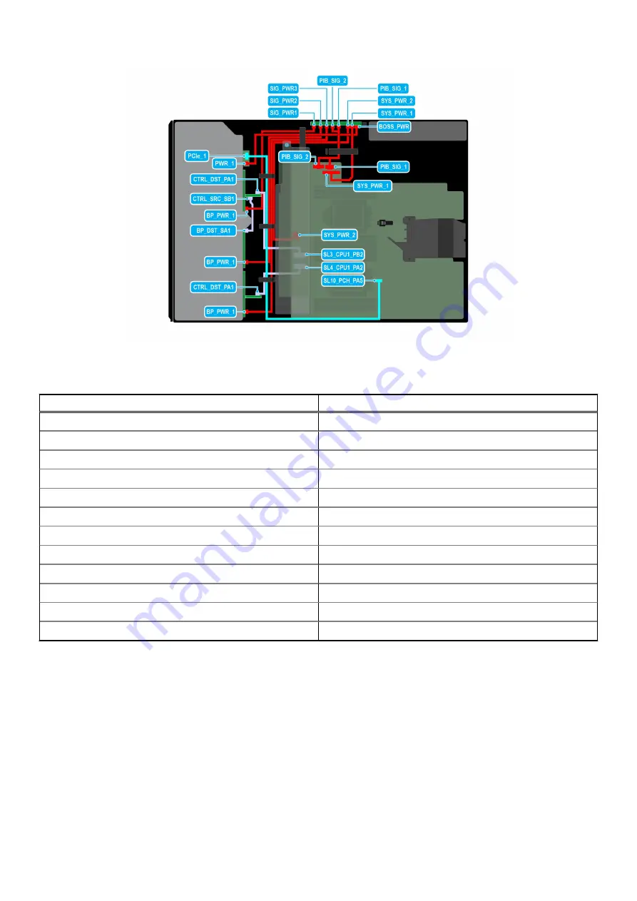
Figure 81. Cable routing - 24 x 2.5-inch SAS with BOSS S2 module
Table 24. Cable routing - 24 x 2.5-inch SAS with BOSS S2 module
From
To
PCIe_1 (Signal connector on BOSS S2 module)
SL10_PCH_PA5 (Signal connector on system board)
PWR_1 (Power connector on BOSS S2 module)
BOSS_PWR (Power connector on PIB)
CTRL_DST_PA1 (Signal connector on PERC)
SL3_CPU1_PB2 (Signal connector on system board)
CTRL_SRC_SB1 (Signal connector on PERC)
BP_DST_SA1 (Signal connector on backplane)
BP_PWR_1 (Power connector on backplane)
SIG_PWR_1 (Power connector on PIB)
BP_PWR_1 (Power connector on backplane)
SIG_PWR_2 (Power connector on PIB)
BP_PWR_1 (Power connector on backplane)
SIG_PWR_3 (Power connector on PIB)
CTRL_DST_PA1 (Signal connector on PERC)
SL4_CPU1_PA2 (Signal connector on system board)
SYS_PWR_1 (Power connector on system board)
SYS_PWR_1 (Power connector on PIB)
SYS_PWR_2 (Power connector on system board)
SYS_PWR_2 (Power connector on PIB)
PIB_SIG_1 (Power connector on system board)
PIB_SIG_1 (Power connector on PIB)
PIB_SIG_2 (Power connector on system board)
PIB_SIG_2 (Power connector on PIB)
86
Installing and removing system components
Содержание E76S
Страница 7: ...Chapter 9 Documentation resources 186 Contents 7 ...
Страница 24: ...Figure 13 Memory information Figure 14 BOSS S2 module 24 PowerEdge T550 system overview ...
Страница 27: ...Figure 24 GPU PowerEdge T550 system overview 27 ...
Страница 73: ...Figure 66 Removing a drive bay Figure 67 Removing a drive bay Installing and removing system components 73 ...
Страница 75: ...Figure 69 Installing a drive bay Figure 70 Installing a drive bay Installing and removing system components 75 ...


