90
Removing and Installing Parts
2
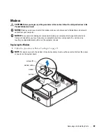
Remove the existing modem:
a
Disconnect the modem cable from the modem.
b
Use a small Phillips screwdriver to remove the two screws securing the modem to the
system board, and set the screws aside.
c
Pull straight up on the attached pull-tab to lift the modem out of its connector on the
system board.
NOTICE:
The connectors are keyed to ensure correct insertion. If you feel resistance, check the
connectors and realign the card.
3
Install the new modem:
a
Align the modem with the screw holes and press the modem into the connector on the
system board.
b
Connect the modem cable to the modem.
c
Use a Phillips screwdriver to replace and tighten the two screws that secure the modem to
the system board.
4
Replace the computer cover (see page 93).
Replacing the External Modem Connector
1
Follow the procedures in "Before You Begin" on page 55.
2
Remove the modem cable from the modem.
3
Remove the existing modem (see page 89).
NOTE:
Note the routing of the modem cable as you remove the modem. You must route the cable
properly when you replace the modem to prevent the cable from being pinched or crimped.
4
Remove the modem cable from the modem.
5
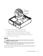
Remove the external modem connector:
a
Remove the screw that secures the external modem connector.
b
Slide the external modem connector away from the slot that holds the modem connector
in place.
c
Lift the modem cable and connector from the computer.
Содержание Dimension 5150C
Страница 8: ...8 Contents ...
Страница 12: ...12 Finding Information ...
Страница 44: ...44 Solving Problems ...
Страница 94: ...94 Removing and Installing Parts ...

