8-4
Dell PowerEdge 2200 Systems User’s Guide
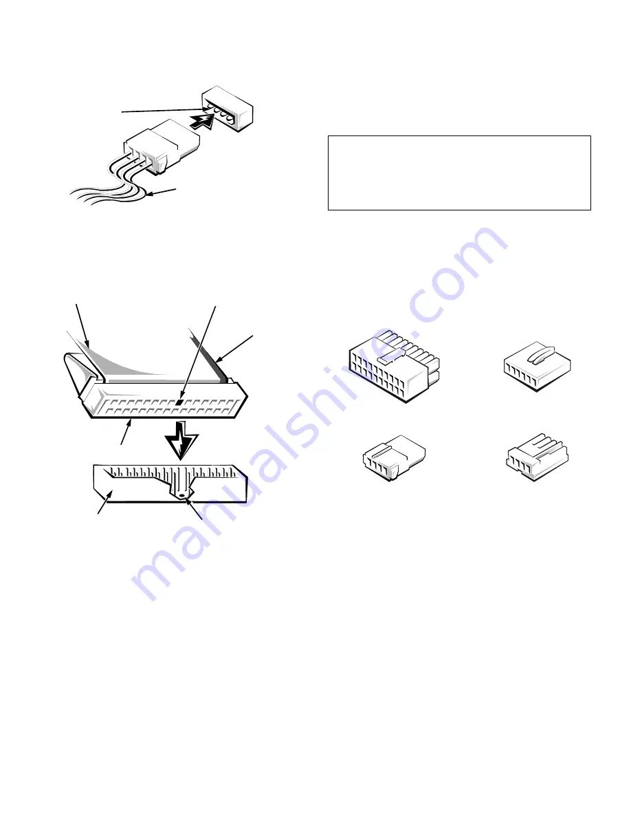
Figure 8-4. Power Connectors
A ribbon cable (see Figure 8-5) functions as the interface
cable for most types of drives.
Figure 8-5. Interface Connectors
Most interface connectors are keyed for correct insertion;
that is, a notch or a missing pin on one connector matches
a tab or a filled-in hole on the other connector. Keying
ensures that the pin-1 wire in the cable (indicated by the
colored strip along one edge of the cable) goes to the pin-1
ends of the connectors on both ends.
The header connector on the drive is usually keyed by the
omission of one of its pins, with the corresponding hole filled
in on the interface cable connector, as shown in Figure 8-5.
DC Power Cables
Figure 8-6 identifies the different types of connectors on the
DC power cables coming from the computer’s power supply.
Before connecting a drive to a power cable, refer to
Figure 8-6 to identify the correct cable connector to use for
the drive.
Figure 8-6. DC Power Cable Connectors
I
nstalling Drives in the External
Bays
The external drive bays (see Figure 8-7) can hold up to
three half-height devices. A diskette drive is standard in
the top bay and a CD-ROM drive is standard in the mid-
dle bay. The lower bay can be used for a SCSI drive or a
drive that requires its own controller card and interface
cable, such as some kinds of tape drives.
power input
connector
on the drive
DC power cable (from
the power supply)
key (cut-off pin)
key (blocked hole)
header connector
interface connector
pull tab
colored
strip on
ribbon
cable
CAUTION: When connecting an interface cable,
match the colored strip to the pin-1 end of the
connector. Reversing the cable prevents the drive
from operating and could damage the controller,
the drive, or both.
system board
connector
5.25-inch drive
connector
3.5-inch drive
connector
system board
connector
Содержание Dimension 2200
Страница 1: ... HOO 3RZHU GJH 6 VWHPV 86 5 6 8 ...
Страница 6: ...viii ...
Страница 10: ...xii ...
Страница 22: ...xxiv ...
Страница 30: ...2 4 Dell PowerEdge 2200 Systems User s Guide ...
Страница 64: ...4 18 Dell PowerEdge 2200 Systems User s Guide ...
Страница 88: ...6 8 Dell PowerEdge 2200 Systems User s Guide ...
Страница 100: ...7 12 Dell PowerEdge 2200 Systems User s Guide ...
Страница 118: ...A 4 Dell PowerEdge 2200 Systems User s Guide ...
Страница 128: ...B 10 Dell PowerEdge 2200 Systems User s Guide ...
Страница 140: ...D 6 Dell PowerEdge Systems 2200 User s Guide ...


