background image

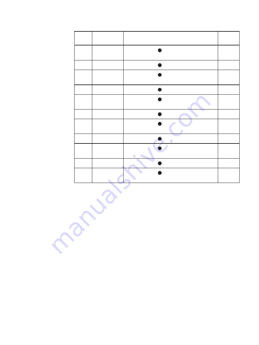
String
(Loop)

I/O - Port

Shelf Port

Length 

a

1

I/O 2 - Port 0

A controller HOST 

 port of the highest number

shelf in V1

2M

2

I/O 3 - Port 0

B controller HOST 

 port of shelf V2.1

2M

2

I/O 6 - Port 1

A controller HOST 

 port of the highest number

shelf in V2

2M

3

I/O 2 - Port 1

B controller HOST 

 port of shelf V3.1

2M

3

I/O 6 - Port 0

A controller HOST 

 port of the highest number

shelf in V3

2M

4

I/O 3 - Port 3

B controller HOST 

 port of shelf V4.1

3M

4

I/O 2 - Port 2

A controller HOST 

 port of the highest number

shelf in V4

3M

5

I/O 3 - Port 2

B controller HOST 

 port of shelf V5.1

3M

5

I/O 6 - Port 2

A controller HOST 

 port of the highest number

shelf in V5

3M

6

I/O 2 - Port 3

B controller HOST 

 port of shelf V6.1

3M

6

I/O 6 - Port 3

A controller HOST 

 port of the highest number

shelf in V6

3M

a. Cable lengths shown are designed for Data Domain racks. Longer cables (up to 5M) can be

used.

Connect Cables and Power on

DD9500 /DD9800


57

Содержание Data Domain DD9500

Страница 1: ...Dell EMC Data Domain DD9500 and DD9800 Systems Version 6 1 Hardware Overview and Installation Guide 302 002 887 REV 02 ...

Страница 2: ...ON AND SPECIFICALLY DISCLAIMS IMPLIED WARRANTIES OF MERCHANTABILITY OR FITNESS FOR A PARTICULAR PURPOSE USE COPYING AND DISTRIBUTION OF ANY DELL SOFTWARE DESCRIBED IN THIS PUBLICATION REQUIRES AN APPLICABLE SOFTWARE LICENSE Dell EMC and other trademarks are trademarks of Dell Inc or its subsidiaries Other trademarks may be the property of their respective owners Published in the USA Dell EMC Hopki...

Страница 3: ...s 32 Storage capacity 33 Install the System in the Rack 37 Unpack the system 38 Install the rack brackets 38 Shelf brackets and cable management assembly 38 Install rail brackets on the Data Domain racks for square or round hole racks 40 Install rail brackets using the adapter hardware for threaded hole racks 43 Install the DD9500 DD9800 system into a rack 45 Mount the cable management assembly 47...

Страница 4: ... and DD9800 with DD Cloud Tier Single node 75 DD9500 and DD9800 with DD Cloud Tier HA 76 DD9500 and DD9800 with ERSO 80 Connecting the HA interconnect 81 Connect data cables on both nodes 82 Power on the systems 83 Install the bezel 84 Configure System For Use 85 Enable administrative communication 86 Accepting the End User License Agreement EULA 88 Run the configuration wizard 88 Configuring the ...

Страница 5: ... Rear of the rack mount rail 49 Node 0 SAS I O module to ES30 host port connector 53 Node 1 SAS I O module to ES30 expansion port connector 54 Cables for ES30 to ES30 connections 55 Cabling for base DD9500 DD9800 systems 58 Cabling for HA DD9500 DD9800 systems in one rack 60 Cabling for HA DD9500 DD9800 systems in two racks 63 Cabling for DD9500 DD9800 systems with DD Cloud Tier Single node or HA ...

Страница 6: ...FIGURES 6 Data Domain DD9500 and DD9800 Systems 6 1 Hardware Overview and Installation Guide ...

Страница 7: ...3 Cables for node 1 to ES30 shelf loop 54 ES30 to ES30 cable options 55 Primary node cabling instructions 59 Standby node cabling instructions 59 Primary node cabling instructions 61 Standby node cabling instructions 61 Primary node cabling instructions 64 Standby node cabling instructions 64 Cables for node 0 and node 1 to DS60 shelf loop 69 Primary node cabling instructions 73 Standby node cabli...

Страница 8: ...TABLES 8 Data Domain DD9500 and DD9800 Systems 6 1 Hardware Overview and Installation Guide ...

Страница 9: ...nt revision history Revision Date Document part number Revision Number Software version Description 02 June 2017 302 002 887 Rev 01 6 1 Editorial revisions 01 October 2016 302 002 887 Rev 01 6 0 Initial publication Revision history 9 ...

Страница 10: ...Revision history 10 Data Domain DD9500 and DD9800 Systems 6 1 Hardware Overview and Installation Guide ...

Страница 11: ...CHAPTER 1 Planning and Site Preparation l Tools and supplies needed 12 l Safety information 12 Planning and Site Preparation 11 ...

Страница 12: ... Tie wraps 4 in and 8 in l recommended Roll of 5 8 inch Velcro cable tie material 3M Scotchmate SJ 3401 or similar Safety information CAUTION l If the system is used in a manner not specified by the manufacturer the protection provided by the equipment may be impaired l The RJ45 sockets on the motherboard PCI cards or I O modules are for Ethernet connection only and must not be connected to a tele...

Страница 13: ...7 lbs 53 2 kg an ES30 expansion shelf weighs up to 68 lbs 30 8 kg and a DS60 shelf weighs up to 225 lbs 90 7 kg CAUTION Data Domain systems are heavy Use at least two people or a mechanical lift to move any system l Do not lift an expansion shelf by the handles on any modules The handles are not designed to support the weight of the populated shelf l To comply with applicable safety emission and t...

Страница 14: ...ded at least three or more similarly weighted items in the rack or unless the rack is bolted to the floor or overhead structure to prevent tipping Planning and Site Preparation 14 Data Domain DD9500 and DD9800 Systems 6 1 Hardware Overview and Installation Guide ...

Страница 15: ...ware Overview l System features 16 l System specifications 16 l DD9500 DD9800 front panel 18 l Rear panel 22 l I O module slot assignments 27 l Internal System Components 30 l Storage capacity 33 Hardware Overview 15 ...

Страница 16: ...nd SAS slots Replaceable I O modules are not hot swappable See I O module slot assignments on page 27 11 I O module Fibre Channel Ethernet and SAS slots Replaceable I O modules are not hot swappable See I O module slot assignments on page 27 Memory l Base 256 GB l Expanded 512 GB 512 GB is required for DD Cloud Tier and Extended Retention HA is supported with both memory configurations l Base 256 ...

Страница 17: ...te 1 1 C per 1000 feet above 7500 feet up to 10 000 feet l Operating humidity 20 to 80 non condensing l Non operating temperature 40 to 149 F 40 to 65 C l Operating acoustic noise Sound power LWAd is 7 7 bels Hardware Overview System specifications 17 ...

Страница 18: ...jector handle 10 Fan tray thumbscrew right Front LED indicators On the front panel to the right of SSD 4 in Slot 3 are 3 LEDs that show high level system status The System Power LED glows blue to show the system is powered on Note The system can have power be plugged in but the blue LEDs are off if the system is powered off The SP Service LED is normally off but glows amber whenever the storage pr...

Страница 19: ... needs service 2 Enclosure Service LED This is normally off but amber light indicates that the enclosure or something within the enclosure the fans SP I O modules management module etc requires service 3 System power LED Blue light indicates system running Hardware Overview Front LED indicators 19 ...

Страница 20: ...re 4 Power button 1 System power LED Blue light indicates system running 2 Power button The LEDs in the front are shown in the following figure Figure 5 Front LEDs 1 SSD LED in slot 0 2 SSD LED in slot 1 3 SSD LED in slot 2 4 SSD LED in slot 3 5 System power LED Blue light indicates system running Hardware Overview 20 Data Domain DD9500 and DD9800 Systems 6 1 Hardware Overview and Installation Gui...

Страница 21: ...ED Solid blue disk ready blinks while busy SSD Bottom LED Dark indicates healthy Solid amber indicates disk fail Solid State Drives SSD A system contains 4 hot swappable 2 5 in 400 GB SSD drives located in the front There are four drive bays numbered 0 3 from left to right A dual drive failure allows the DD9500 DD9800 system to operate without disruption Each drive has a blue colored power LED and...

Страница 22: ...es numbered 0 through 11 from left to right The photo shows the hardware features and interfaces on the rear of the system Figure 7 Features on rear of chassis 1 Power supply units 2 Serial number tag 3 Management module 4 NVRAM and IO modules slots 0 11 The figure shows the location of the serial number tag on the left of the management module Figure 8 Serial number tag location Hardware Overview...

Страница 23: ...U0 and PSU1 should be attached to one AC source PSU2 and PSU3 should be attached to the other AC source The AC power plugs are located to the right of each power supply The wire clips for the AC cords hold the cords in place The wire clips must be disengaged before disconnecting the AC power to each power supply Figure 9 Four power supplies Management module The following figure shows the location...

Страница 24: ... Right blue thumbscrew to loosen the management module Figure 11 1000BaseT Ethernet ports Lower left port physical 0 logical ethMa Top left port physical 1 logical ethMb Lower right port physical 2 logical ethMc Top right port physical 3 logical ethMd Rear LED Indicators The rear elements containing LEDs include each power supply each I O module and the management module Hardware Overview 24 Data ...

Страница 25: ... Module LEDS The power supply LEDs include l AC LED on top l DC LED in the middle l Service Required LED on the bottom Figure 13 Power supply LEDs Table 5 Rear LED status indicators Part Description or Location State Power supply AC LED Steady green indicates normal AC input power Hardware Overview Rear LED Indicators 25 ...

Страница 26: ...d port Ethernet 10GBase CX1 Direct Attach Copper with SPF module l Quad port Ethernet 10GBase T Copper l Dual port 16 Gbps Fibre Channel l Quad port 6 Gbps SAS I O module port physical mapping I O module ports are numbered starting with 0 When the I O modules are inserted vertically into the system chassis port 0 is on the bottom I O module port logical mapping The numerical port labels on the I O...

Страница 27: ...e Up to four FC I O modules may be installed The optional virtual tape library VTL feature requires at least one FC I O module Boost over Fibre Channel is an optional feature and requires at least one FC I O module A maximum of four FC I O modules may be installed in a system using either VTL or the Boost protocol or a combination of both protocols SAS I O modules DD9500 DD9800 systems have three ...

Страница 28: ...rnet or empty Fibre Channel FC Ethernet or empty Fibre Channel FC Ethernet or empty Fibre Channel FC Ethernet or empty 2 SAS SAS SAS SAS 3 SAS SAS SAS SAS 4 FC Ethernet or empty FC Ethernet or empty FC Ethernet or empty FC Ethernet or empty 5 FC Ethernet or empty FC Ethernet or empty FC Ethernet or empty FC Ethernet or empty 6 SAS SAS SAS SAS 7 FC Ethernet or empty FC Ethernet or empty FC Ethernet...

Страница 29: ...is a fifth Ethernet module but it is reserved for communication between the two nodes of an HA pair and is not available for host connections The maximum number of I O modules including both mandatory and optional I O modules supported in a DD9500 or DD9800 system varies by configuration l Single node 10 l HA 10 l DD Extended Retention 10 l DD Cloud Tier 10 l HA DD Cloud Tier 11 Three I O module s...

Страница 30: ...y with fan modules The SP module also contains the 4 CPUs which cannot be removed or replaced l The memory risers tray which contains 8 memory risers with DIMMs can be accessed from the front of the SP module The memory risers are not hot swappable l The fan tray which contains 8 fan modules can be accessed from the front of the SP module The fans are hot swappable The DIMMS can be accessed by pul...

Страница 31: ...Figure 15 SP module Figure 16 Releasing a memory riser 1 Left riser card ejector handle 2 Release button 3 Right riser card ejector handle Hardware Overview Internal System Components 31 ...

Страница 32: ...oud Tier DD9500 32 x 8 GB DIMMs 256 GB 32 x 8 GB DIMMs 16 x 16 GB DIMMs 512 GB 32 x 8 GB DIMMs 16 x 16 GB DIMMs 512 GB DD9800 32 x 8 GB DIMMs 256 GB 32 x 8 GB DIMMs 32 x 16 GB DIMMS 768 GB 32 x 8 GB DIMMs 32 x 16 GB DIMMS 768 GB Cooling Fans A system contains 8 hot swappable cooling fans in a 7 1 redundant configuration located in the front of the system within a movable fan tray The fans provide ...

Страница 33: ... 2 calculation Table 10 DD9500 DD9800 storage capacity System Installed Memory Internal Disks Raw Storage Base 10 Data Storage Space Base 2 Calculation Data Storage Space Base 10 Calculation DD9500 3 SAS I O modules 256 GB 2 5 in 4 x 400 GB SATA SSD No User Data 540 TB external 392 9 TiB 432 TB DD9500 3 SAS I O modules 512 GB 2 5 in 4 x 400 GB SATA SSD No User Data 1 080 TB external 786 8 TiB 864 ...

Страница 34: ...0 Note For information about Data Domain expansion shelves and guidelines on using a mixture of shelves see the Data Domain ES30 Expansion Shelf Hardware Guide and Data Domain DS60 Expansion Shelf Hardware Guide Table 11 DD9500 DD9800 with ES30 SAS shelves DD9500 DD9500 DD9800 DD9800 Memory GB 256 512 256 768 SAS I O modules x ports per module 3x4 3x4 3x4 3x4 ES30 support TB SAS 30 45 60 SAS 30 45...

Страница 35: ...9500 DD9800 DD9800 Memory GB 256 512 256 768 SAS I O modules x ports per module 3x4 3x4 3x4 3x4 DS60 support TB SAS 45 60 SAS 45 60 SAS 45 60 SAS 45 60 Maximum shelves per set 4 4 4 4 Maximum number of sets 6 6 6 6 Hardware Overview Storage capacity 35 ...

Страница 36: ...Hardware Overview 36 Data Domain DD9500 and DD9800 Systems 6 1 Hardware Overview and Installation Guide ...

Страница 37: ...ludes the following topics l Unpack the system 38 l Install the rack brackets 38 l Install the DD9500 DD9800 system into a rack 45 l Mount the cable management assembly 47 l Installing the expansion shelves into the racks 49 Install the System in the Rack 37 ...

Страница 38: ...splays warning labels Figure 18 Warning about lifting the system 3 Remove expansion shelves and their bezels from the shipping packages Install the rack brackets Data Domain systems are installed into racks using the rail bracket hardware Shelf brackets and cable management assembly The rack mounting kits are compatible with racks that have front to rear post spacing between 24 inches and 36 inche...

Страница 39: ...ight outside bracket A cable management assembly CMA for organization of cables at the rear of the system is already installed onto the DD9500 DD9800 system on a Data Domain rack For field installed systems the CMA is shipped with the DD9500 DD9800 system Install the System in the Rack Shelf brackets and cable management assembly 39 ...

Страница 40: ... Installation and Setup Guide for your system l For HA systems n Mount node 0 such that the bottom of the chassis aligns with the 13U mark in the rack n Mount node 1 such that the bottom of the chassis aligns with the 18U mark in the rack Procedure 1 At each rack post determine the vertical position in the rack where the brackets are to be installed The top most mounting hole for a particular rack...

Страница 41: ... five screw holes The picture shows two screws attached to the rear rack post Figure 22 Insert screw in the back CAUTION If the bracket is mounted in holes that are not vertically aligned from front to back the bracket may be damaged and mounting will not be secure 4 Pull the adjustable sliding part of the bracket towards the front until it is close to but not touching the front of the rack Instal...

Страница 42: ...e Figure 24 Attach bracket to front of rack 6 Verify that the bracket is level 7 Repeat the steps to attach the remaining bracket to the other side of the rack 8 After installing both brackets make sure that they are level with one another Install the System in the Rack 42 Data Domain DD9500 and DD9800 Systems 6 1 Hardware Overview and Installation Guide ...

Страница 43: ...are M5 M6 10 32 or 12 24 l The adapter hardware is shipped in the rack mount kit l You will need a long handled screwdriver with a shank diameter less than 7 0 mm and the wrench included in the kit to tighten the nuts Procedure 1 Locate the two adapters from the rail kit Figure 25 Adapters 1 Long adapter 2 Short adapter 2 Attach the long adapter to the front of each rail using M5 screws Install th...

Страница 44: ...k For example the 10 32 threaded hole rack would require the installation of the 10 32 screws Install the screws in the appropriate locations until they are tight against the rack 6 As needed select the bracket marked right or left Orientation assumes you are facing the front of the rack 7 Slide the adjustable part of the bracket partly open 8 Attach the first rail to the rack as follows a Hold th...

Страница 45: ...sure that they are level with one another 11 For HA systems repeat this procedure for the second node Install the DD9500 DD9800 system into a rack CAUTION Data Domain systems are heavy Always use two people or a mechanical lift to move a system The chassis displays warning signs Figure 28 Warning about lifting the system Install the System in the Rack Install the DD9500 DD9800 system into a rack 4...

Страница 46: ...e lengths for some configurations 2 From the front of the rack lift the DD9500 DD9800 system using the handles supplied for lifting to install the system in the rack in the correct location 3 At each side align the bottom of the chassis with the lip of each installed rack bracket 4 Carefully slide the chassis into the rack and remove the back handles while supporting the chassis weight Continue to...

Страница 47: ...eld installed systems the CMA is shipped separately Note For non Data Domain racks it is acceptable to use the cable management products provided by the rack vendor Install the Data Domain cable management assembly CMA Procedure 1 Take out the cable management assembly CMA from its packaging 2 Locate the two blue knobs on the left and right sides of the CMA in the back which you will need to pull ...

Страница 48: ...is pulled away from the side of the bracket to fit in the rail slot Figure 32 Data Domain cable management assembly back inside 4 Locate the slots and the hole in the Data Domain rail to attach the CMA by following the arrows in the picture Align and insert the CMA tabs in the slots and the blue knob in the hole of the rail bracket on both sides Install the System in the Rack 48 Data Domain DD9500...

Страница 49: ... module and the powers supply units for removal and replacement Just adjust the CMA arms 8 For HA systems repeat this procedure to install the CMA for the second node Installing the expansion shelves into the racks CAUTION l Data Domain systems are heavy Always use two people or a mechanical lift to move and install a Data Domain system Use caution to install the expansion shelves l Ensure that ea...

Страница 50: ...ves connected to the system l Data Domain recommends installing the SSD shelf in the V1 1 positon but if that is not possible the shelf can be placed in a different location in the rack so long as cables of sufficient length are available Note V1 1 is recommended for better performance because this will the 1st hop where data will be written If the SSD shelf is connected to the last enclosure in a...

Страница 51: ... ES30 cable information 52 l Connecting multiple ES30 shelves to the DD9500 DD9800 system 56 l DS60 cable information 69 l Connecting multiple DS60 shelves to the DD9500 DD9800 system 70 l Connecting the HA interconnect 81 l Connect data cables on both nodes 82 l Power on the systems 83 l Install the bezel 84 Connect Cables and Power on 51 ...

Страница 52: ...6 to connect a DD9500 system l Refer to the diagrams in the Connecting multiple DS60 shelves to the DD9500 DD9800 system on page 70 to connect a DD9500 system For more information about specific shelf cabling rules and guidelines for different types of shelves see l Data Domain ES30 and FS15 Expansion Shelf Hardware Guide l Data Domain DS60 Expansion Shelf Hardware Guide ES30 cable information The...

Страница 53: ...0 shelf loop HD mini SAS connector on controller SFF 8088 connector keyed for host port on ES30 Cable model code Part number Cable length X SAS HDMS2 038 003 810 2 m 79 in X SAS HDMS3 038 003 811 3 m 118 in X SAS HDMS5 038 003 813 5 m 196 in Connect Cables and Power on ES30 cable information 53 ...

Страница 54: ...D mini SAS connector on controller SFF 8088 connector keyed for expansion port on ES30 Cable model Part number Cable length X HA ES30 SAS 2 038 004 108 2 m 79 in X HA ES30 SAS 5 038 004 111 5 m 196 in Connect Cables and Power on 54 Data Domain DD9500 and DD9800 Systems 6 1 Hardware Overview and Installation Guide ...

Страница 55: ...one end keyed for host ports and the other keyed for expansion ports Cable model Part number Cable length X SAS MSMS1 038 003 786 1 m 39 in X SAS MSMS2 038 003 787 2 m 79 in X SAS MSMS3 038 003 751 3 m 118 in X SAS MSMS4 038 003 628 4 m 158 in X SAS MSMS5 038 003 666 5 m 196 in Connect Cables and Power on ES30 cable information 55 ...

Страница 56: ... is not possible the shelf can be placed in a different location in the rack so long as cables of sufficient length are available Note V1 1 is recommended for better performance because this will the 1st hop where data will be written If the SSD shelf is connected to the last enclosure in a chain then each read write request has to go through many hops which introduces latency issues when compared...

Страница 57: ...est number shelf in V3 2M 4 I O 3 Port 3 B controller HOST port of shelf V4 1 3M 4 I O 2 Port 2 A controller HOST port of the highest number shelf in V4 3M 5 I O 3 Port 2 B controller HOST port of shelf V5 1 3M 5 I O 6 Port 2 A controller HOST port of the highest number shelf in V5 3M 6 I O 2 Port 3 B controller HOST port of shelf V6 1 3M 6 I O 6 Port 3 A controller HOST port of the highest number...

Страница 58: ...g for base DD9500 DD9800 systems DD9500 DD9800 with HA one rack For an HA DD9500 DD9800 pair in one rack Connect Cables and Power on 58 Data Domain DD9500 and DD9800 Systems 6 1 Hardware Overview and Installation Guide ...

Страница 59: ...r Data Domain racks Longer cables up to 5M can be used Table 17 Standby node cabling instructions String Loop I O Port Shelf Port Length a 1 I O 3 Port 1 A controller EXPANSION port of shelf V1 1 2M 1 I O 2 Port 0 B controller EXPANSION port of the highest number shelf in V1 2M 2 I O 3 Port 0 A controller EXPANSION port of shelf V2 1 2M 2 I O 6 Port 1 B controller EXPANSION port of the highest num...

Страница 60: ...HA DD9500 DD9800 systems in one rack DD9500 DD9800 with HA two racks For an HA DD9500 DD9800 pair in two racks Connect Cables and Power on 60 Data Domain DD9500 and DD9800 Systems 6 1 Hardware Overview and Installation Guide ...

Страница 61: ... controller HOST port of shelf V5 1 3M 5 I O 6 Port 2 A controller HOST port of the highest number shelf in V5 3M 6 I O 2 Port 3 B controller HOST port of shelf V6 1 3M 6 I O 6 Port 3 A controller HOST port of the highest number shelf in V6 3M a Cable lengths shown are designed for Data Domain racks Longer cables up to 5M can be used Table 19 Standby node cabling instructions String Loop I O Port ...

Страница 62: ...shelf in V4 3M 5 I O 3 Port 2 A controller EXPANSION port of shelf V5 1 3M 5 I O 6 Port 2 B controller EXPANSION port of the highest number shelf in V5 3M 6 I O 2 Port 3 A controller EXPANSION port of shelf V6 1 3M 6 I O 6 Port 3 B controller EXPANSION port of the highest number shelf in V6 3M a Cable lengths shown are designed for Data Domain racks Longer cables up to 5M can be used Connect Cable...

Страница 63: ...9500 DD9800 systems in two racks DD9500 DD9800 with DD Cloud Tier Single node or HA For a DD9500 DD9800 system with DD Cloud Tier Single node or HA Connect Cables and Power on DD9500 DD9800 with DD Cloud Tier Single node or HA 63 ...

Страница 64: ...helf V5 1 3M 5 I O 9 Port 2 A controller HOST port of the highest number shelf in V5 3M 6 I O 2 Port 3 B controller HOST port of shelf V6 1 3M 6 I O 6 Port 3 A controller HOST port of the highest number shelf in V6 3M a Cable lengths shown are designed for Data Domain racks Longer cables up to 5M can be used Table 21 Standby node cabling instructions String Loop I O Port Shelf Port Length a 1 I O ...

Страница 65: ... highest number shelf in V4 3M 5 I O 3 Port 2 A controller EXPANSION port of shelf V5 1 3M 5 I O 9 Port 2 B controller EXPANSION port of the highest number shelf in V5 3M 6 I O 2 Port 3 A controller EXPANSION port of shelf V6 1 3M 6 I O 6 Port 3 B controller EXPANSION port of the highest number shelf in V6 3M a Cable lengths shown are designed for Data Domain racks Longer cables up to 5M can be us...

Страница 66: ...D9500 DD9800 system with ERSO String Loop I O Port Shelf Port Length a 1 I O 3 Port 1 B controller HOST port of shelf V1 1 2M 1 I O 2 Port 0 A controller HOST port of the highest number shelf in V1 5M Connect Cables and Power on 66 Data Domain DD9500 and DD9800 Systems 6 1 Hardware Overview and Installation Guide ...

Страница 67: ...controller HOST port of shelf V5 1 3M 5 I O 9 Port 2 A controller HOST port of the highest number shelf in V5 5M 6 I O 2 Port 3 B controller HOST port of shelf V6 1 3M 6 I O 6 Port 3 A controller HOST port of the highest number shelf in V6 5M 7 I O 9 Port 0 B controller HOST port of shelf V7 1 3M 7 I O 6 Port 1 A controller HOST port of the highest number shelf in V7 5M 8 I O 6 Port 2 B controller...

Страница 68: ...Figure 41 Cabling for DD9500 DD9800 systems with ERSO Connect Cables and Power on 68 Data Domain DD9500 and DD9800 Systems 6 1 Hardware Overview and Installation Guide ...

Страница 69: ...DS60 connector Table 22 Cables for node 0 and node 1 to DS60 shelf loop HD mini SAS connector on controller and enclosure Cable model code Part number Cable length XC DS60 SAS 3M 038 004 380 01 3 m 118 in XC DS60 SAS 4M 038 000 212 00 4 m 158 in XC DS60 SAS 5M 038 000 214 00 5 m 196 in Connect Cables and Power on DS60 cable information 69 ...

Страница 70: ...t location in the rack so long as cables of sufficient length are available Note V1 1 is recommended for better performance because this will the 1st hop where data will be written If the SSD shelf is connected to the last enclosure in a chain then each read write request has to go through many hops which introduces latency issues when compared to when the SSD shelf is on the 1st shelf of a chain ...

Страница 71: ... highest number shelf in V3 2M 4 I O 2 Port 2 A controller port 0 of shelf V4 1 2M 4 I O 3 Port 2 B controller port 0 of the highest number shelf in V4 5M 5 I O 6 Port 3 A controller HOST port of the SSD shelf 2M 5 I O 3 Port 3 B controller HOST port of the SSD shelf 2M a Cable lengths shown are designed for Data Domain racks Longer cables up to 5M can be used Connect Cables and Power on DD9500 DD...

Страница 72: ...Figure 43 Cabling for base DD9500 and DD9800 systems Connect Cables and Power on 72 Data Domain DD9500 and DD9800 Systems 6 1 Hardware Overview and Installation Guide ...

Страница 73: ...2M a Cable lengths shown are designed for Data Domain racks Longer cables up to 5M can be used Table 24 Standby node cabling instructions String Loop I O Port Shelf Port Length a 1 I O 6 Port 0 B controller port 2 of shelf V1 1 2M 1 I O 2 Port 1 A controller port 2 of the highest number shelf in V1 2M 2 I O 3 Port 0 B controller port 2 of shelf V2 1 2M 2 I O 2 Port 0 A controller port 2 of the hig...

Страница 74: ...Figure 44 Cabling for HA DD9500 and DD9800systems Connect Cables and Power on 74 Data Domain DD9500 and DD9800 Systems 6 1 Hardware Overview and Installation Guide ...

Страница 75: ...0 of shelf V4 1 5M 4 I O 3 Port 2 B controller port 0 of the highest number shelf in V4 5M 5 I O 2 Port 3 A controller port 0 of shelf V5 1 5M 5 I O 9 Port 0 B controller port 0 of the highest number shelf in V5 5M 6 I O 6 Port 3 A controller HOST port of the SSD shelf or DD Cloud Tier metadata shelf 2M 6 I O 3 Port 3 B controller HOST port of the SSD shelf or DD Cloud Tier metadata shelf 2M 7 I O...

Страница 76: ...9800 systems with DD Cloud Tier DD9500 and DD9800 with DD Cloud Tier HA For an HA DD9500 and DD9800 pair with DD Cloud Tier Connect Cables and Power on 76 Data Domain DD9500 and DD9800 Systems 6 1 Hardware Overview and Installation Guide ...

Страница 77: ...adata shelf 2M 6 I O 6 Port 2 B controller HOST port of the SSD shelf or DD Cloud Tier metadata shelf 2M a Cable lengths shown are designed for Data Domain racks Longer cables up to 5M can be used Table 26 Standby node cabling instructions String Loop I O Port Shelf Port Length a 1 I O 6 Port 0 B controller port 2 of shelf V1 1 2M 1 I O 2 Port 1 A controller port 2 of the highest number shelf in V...

Страница 78: ...SSD shelf or DD Cloud Tier metadata shelf 2M 6 I O 6 Port 2 B controller EXPANSION port of the SSD shelf or DD Cloud Tier metadata shelf 2M a Cable lengths shown are designed for Data Domain racks Longer cables up to 5M can be used Connect Cables and Power on 78 Data Domain DD9500 and DD9800 Systems 6 1 Hardware Overview and Installation Guide ...

Страница 79: ...Figure 46 Cabling for HA DD9500 and DD9800 systems with DD Cloud Tier Connect Cables and Power on DD9500 and DD9800 with DD Cloud Tier HA 79 ...

Страница 80: ...st number shelf in V4 5M 5 I O 2 Port 3 A controller port 0 of shelf V5 1 5M 5 I O 9 Port 0 B controller port 0 of the highest number shelf in V5 5M 6 I O 9 Port 3 A controller port 0 of shelf V6 1 5M 6 I O 6 Port 1 B controller port 0 of the highest number shelf in V6 5M 7 I O 6 Port 2 A controller port 0 of shelf V7 1 5M 7 I O 9 Port 1 B controller port 0 of the highest number shelf in V7 5M 8 I...

Страница 81: ...O module in slot 11 of each node in the HA pair This connection between the two nodes provides the standby node with the information it needs to failover if the active node suffers a failure and maintain the connections to hosts and clients after the failover is complete Connect Cables and Power on Connecting the HA interconnect 81 ...

Страница 82: ... module in node 1 slot 11 4 Cable port 2 of the interconnect I O module in node 0 slot 11 to port 2 of the interconnect I O module in node 1 slot 11 5 Cable port 3 of the interconnect I O module in node 0 slot 11 to port 3 of the interconnect I O module in node 1 slot 11 Connect data cables on both nodes Note The data cabling for both nodes of the HA pair must be identical 1 Enable data transfer E...

Страница 83: ...les to each expansion shelf receptacle and attach the retention clips 2 Provide power to power on each expansion shelf The shelves power on when plugged in Ensure that each shelf power cable is connected to a different power source Note Wait approximately 3 minutes after all expansion shelves are powered on before powering on the controller 3 Provide power to power on the controller The system pow...

Страница 84: ...asping both hand holds and pressing toward the center of the bezel until the latches attach to the sides of the chassis The red circles identify the latches on each bezel Make sure the handhold locks lock into place Connect Cables and Power on 84 Data Domain DD9500 and DD9800 Systems 6 1 Hardware Overview and Installation Guide ...

Страница 85: ...he following topics l Enable administrative communication 86 l Accepting the End User License Agreement EULA 88 l Run the configuration wizard 88 l Configuring additional system parameters 90 l Configure HA for new installations 91 Configure System For Use 85 ...

Страница 86: ... work for the DD9500 DD9800 system Launch a terminal emulation program from your computer and configure the following communication settings Table 27 Communications settings Setting Value Baud rate 115200 Data bits 8 Stop bits 1 Parity None Flow control None Emulation VT 100 3 Select Enter on your keyboard to activate the console Note If you do not see the prompt on your terminal to log in then co...

Страница 87: ...on the standby node to match the system password on the active node however that synchronization is not set until the HA configuration is complete If the HA configuration fails or if there is a need to access either node before the HA configuration is complete use the serial number of each node as the password Note If you enter an incorrect password four consecutive times the system locks out the ...

Страница 88: ...of questions that provide just enough information for initial system configuration and basic network connectivity Note You can initiate the CLI configuration wizard manually by entering the config setup command Configuring the network Procedure 1 Enter yes to configure the system for network connectivity Network Configuration Configure Network at this time yes no no yes 2 Enter yes to configure DH...

Страница 89: ...nter to continue IPV6 Default Gateway Enter the ipv6 default gateway IP address 8 Enter up to three DNS servers to use for resolving host names to IP addresses Use a comma separated or space separated list Enter a space for no DNS servers Or accept the IP addresses of the DNS servers if the system was able to discover them DNS Servers Enter the DNS Server list zero one two or three IP addresses 19...

Страница 90: ...Data Center Lab 5000 Apple Drive Suite 130 Dallas Tx The System Location is Dallas Regional Data Center Lab 5000 Apple Drive Suite 130 Dallas Tx 3 To add one or more time servers enter Note HA configuration requires that the two nodes maintain a time difference of no more than 10 seconds ntp add timeserver 192 168 101 1 Remote Time Servers 192 168 10 1 4 To enable the NTP daemon enter ntp enable N...

Страница 91: ...te If the HA configuration fails or if there is a need to access either node before the HA configuration is complete use the serial number of each node as the password Procedure 1 Identify which node will serve as the active node 2 On the active node create the HA pairing Run the following command ha create peer ipaddr hostname ha name ha system name Note l Specify the hostname or the IP address o...

Страница 92: ... float option is the only way to configure a floating IP address There is no method available in Data Domain System Manager to configure a floating IP address net config eth4a 2 2 2 1 netmask 255 255 255 0 type floating Configure System For Use 92 Data Domain DD9500 and DD9800 Systems 6 1 Hardware Overview and Installation Guide ...

Отзывы: