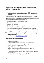
8 If there are any issues, error codes are displayed.
Note the error code and validation number and contact Dell.
Diagnostics
Power and battery-status light: Indicates the power and battery-charge status.
Solid amber – Computer is running on battery and the battery has less than 10
percent charge.
User-defined color (AC mode) – Power adapter is connected and the battery is
fully charged.
User-defined color (Battery mode) – Computer is running on battery and the
battery has more than 10 percent charge.
User-defined color (Breath) – Computer is in sleep state.
Off – Computer is in hibernation, or turned off.
The power and battery-status light blinks red and blue along with beep codes
indicating failures.
For example, the power and battery-status light blinks red two times followed by a
pause, and then blinks blue three times followed by a pause. This 2,3 pattern
continues until the computer is turned off indicating no memory or RAM is
detected.
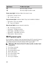
The following table shows different light patterns and what they indicate.
Table 12. Diagnostics
Light Pattern
Problem description
2,1
CPU failure
2,2
System board: BIOS and ROM failure
2,3
No memory or RAM detected
2,4
Memory or RAM failure
2,5
Invalid memory installed
2,6
System board or chipset error
2,7
LCD failure
3,1
CMOS battery failure
3,2
PCI/video card failure
147
Содержание Alienware 17 R5
Страница 20: ...5 Replace the six screws M2 5x13 that secure the base cover to the computer base 20 ...
Страница 23: ...7 Disconnect the interposer from the hard drive 23 ...
Страница 26: ...7 Connect the hard drive cable to the system board Post requisites Replace the base cover 26 ...
Страница 32: ...3 Slide and remove the solid state drive from the solid state drive slot 32 ...
Страница 36: ...2 Slide and remove the memory module from the memory module slot 36 ...
Страница 38: ...Post requisites Replace the base cover 38 ...
Страница 40: ...3 Pull the rear I O cover from the computer base 40 ...
Страница 42: ...Post requisites Replace the base cover 42 ...
Страница 46: ...6 Lift the computer base off the palm rest assembly 46 ...
Страница 51: ...5 Gently peel the coin cell battery along with its cable off the palm rest assembly 51 ...
Страница 55: ...3 Lift the speakers along with its cable off the palm rest assembly 55 ...
Страница 59: ...4 Turn the I O board over 5 Disconnect the subwoofer cable 59 ...
Страница 60: ...6 Lift the I O board off the palm rest assembly 60 ...
Страница 64: ...2 Lift the subwoofer along with its cable off the palm rest assembly 64 ...
Страница 72: ...25 After performing all the above steps you are left with the system board 72 ...
Страница 80: ...8 Lift the heat sink assembly off the system board 80 ...
Страница 85: ...5 Remove the cable from the routing guides on the palm rest assembly 85 ...
Страница 89: ...2 Lift the power button board along with its cable off the palm rest assembly 89 ...
Страница 95: ...7 Lift the display assembly off the computer base 95 ...
Страница 100: ...2 Lift the battery off the palm rest assembly 100 ...
Страница 108: ...7 Replace the base cover 108 ...
Страница 111: ...4 Peel off the macro keys cable and macro keys backlight cable from the keyboard 111 ...
Страница 112: ...5 Lift the keyboard at an angle and remove it from the tabs on the palm rest assembly 112 ...
Страница 116: ...13 Replace the base cover 116 ...
Страница 118: ...Procedure Lift the macro keys at an angle and release it from the tabs on the palm rest assembly 118 ...
Страница 122: ...Procedure After performing all the prerequisites we are left with the palm rest 122 ...
Страница 124: ...19 Replace the base cover 124 ...

