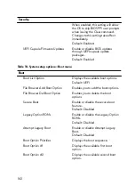
Table 9. System setup options—Security menu
Security
Unlock Setup Status
Displays if the setup status is
unlocked.
Admin Password Status
Displays if the administrator password
is clear or set.
Default: Not set
System Password Status
Displays if the system password is
clear or set.
Default: Not set
HDD Password Status
Displays if the HDD password is clear
or set.
Default: Not set
Admin Password
Enables you to set the administrator
password. The administrator password
controls access to the system setup
utility.
System Password
Enables you to set the system
password. The system password
controls access to the computer at
boot.
HDD password
Enables you to set, change or delete
the hard-disk drive password.
Password Change
Enables you to permit or deny system
password or HDD password changes.
Default: Permitted
Computrace
Enable or disable the BIOS module
interface of the optional Computrace
Service from Absolute Software.
Default: Activate
Firmware TPM
Enables you to enable or disable the
firmware TPM function.
Default: Enabled
PPI Bypass for Clear Command
Enables you to control the TPM
Physical Presence Interface (PPI).
141
Содержание Alienware 17 R5
Страница 20: ...5 Replace the six screws M2 5x13 that secure the base cover to the computer base 20 ...
Страница 23: ...7 Disconnect the interposer from the hard drive 23 ...
Страница 26: ...7 Connect the hard drive cable to the system board Post requisites Replace the base cover 26 ...
Страница 32: ...3 Slide and remove the solid state drive from the solid state drive slot 32 ...
Страница 36: ...2 Slide and remove the memory module from the memory module slot 36 ...
Страница 38: ...Post requisites Replace the base cover 38 ...
Страница 40: ...3 Pull the rear I O cover from the computer base 40 ...
Страница 42: ...Post requisites Replace the base cover 42 ...
Страница 46: ...6 Lift the computer base off the palm rest assembly 46 ...
Страница 51: ...5 Gently peel the coin cell battery along with its cable off the palm rest assembly 51 ...
Страница 55: ...3 Lift the speakers along with its cable off the palm rest assembly 55 ...
Страница 59: ...4 Turn the I O board over 5 Disconnect the subwoofer cable 59 ...
Страница 60: ...6 Lift the I O board off the palm rest assembly 60 ...
Страница 64: ...2 Lift the subwoofer along with its cable off the palm rest assembly 64 ...
Страница 72: ...25 After performing all the above steps you are left with the system board 72 ...
Страница 80: ...8 Lift the heat sink assembly off the system board 80 ...
Страница 85: ...5 Remove the cable from the routing guides on the palm rest assembly 85 ...
Страница 89: ...2 Lift the power button board along with its cable off the palm rest assembly 89 ...
Страница 95: ...7 Lift the display assembly off the computer base 95 ...
Страница 100: ...2 Lift the battery off the palm rest assembly 100 ...
Страница 108: ...7 Replace the base cover 108 ...
Страница 111: ...4 Peel off the macro keys cable and macro keys backlight cable from the keyboard 111 ...
Страница 112: ...5 Lift the keyboard at an angle and remove it from the tabs on the palm rest assembly 112 ...
Страница 116: ...13 Replace the base cover 116 ...
Страница 118: ...Procedure Lift the macro keys at an angle and release it from the tabs on the palm rest assembly 118 ...
Страница 122: ...Procedure After performing all the prerequisites we are left with the palm rest 122 ...
Страница 124: ...19 Replace the base cover 124 ...

