background image

LEDs:

Temperature monitoring

Software-readable thermal monitor

Power management monitoring

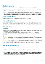
System ground connector

Physical dimensions

The N3200-ON Series switches have the following physical dimensions:

1.71 in x 17.09 in x 15.75 in (H x W x D)

43.5 mm x 434 mm x 400 mm (H x W x D)

LED display

The N3200-ON Series switch includes LED displays on the PSU side of the switch. This section describes open networking installation 
environment (ONIE) LED behaviors. Some LED behaviors may change after you install your software.

LED behavior

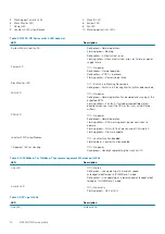
The following N3200-ON Series switch LED behavior is seen during ONIE operations:

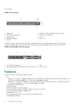
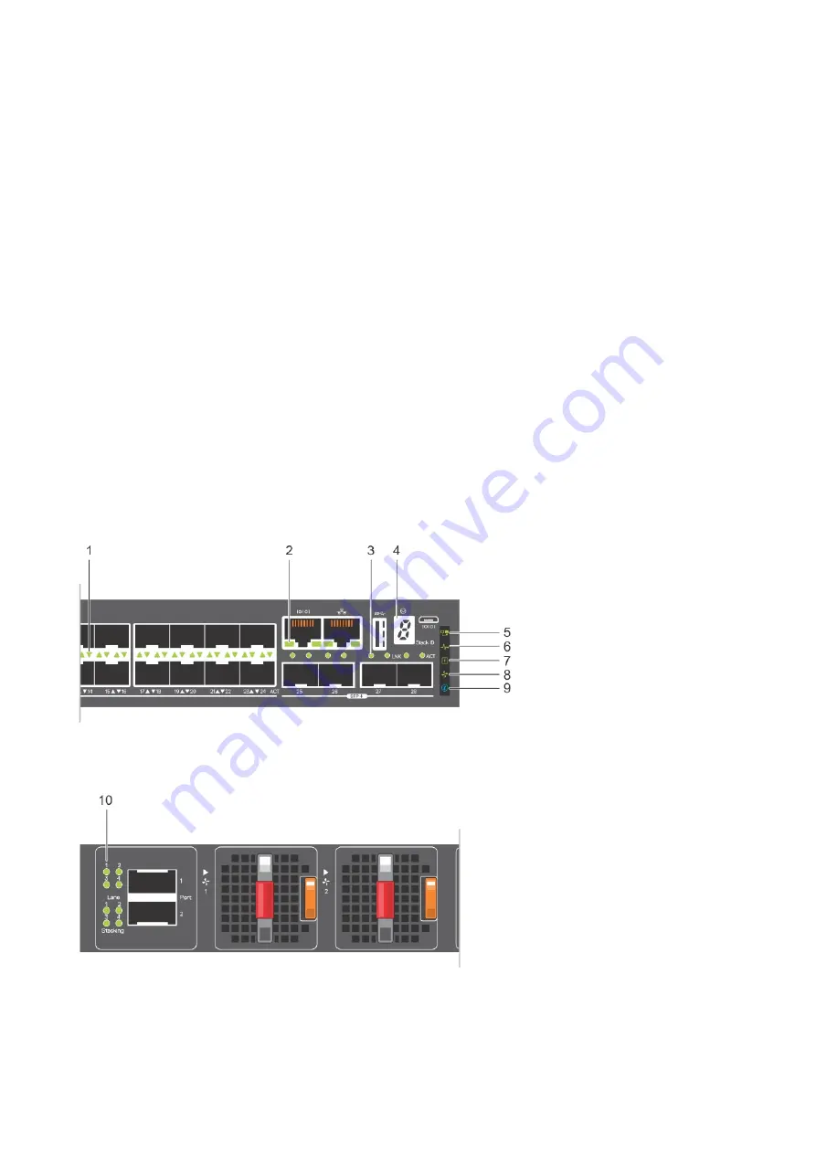
N3248P-ON and N3248PXE-ON LEDs

1. Port activity LEDs

2. Management port activity LEDs

N3200-ON Series switch

9

Содержание PowerSwitch N3200-ON Series

Страница 1: ...Dell EMC PowerSwitch N3200 ON Series Installation Guide October 2019...

Страница 2: ...mage to hardware or loss of data and tells you how to avoid the problem WARNING A WARNING indicates a potential for property damage personal injury or death 2019 Dell Inc or its subsidiaries All right...

Страница 3: ...allation 16 Unpack 16 Unpacking Steps 17 Rack or cabinet hardware installation 17 Ground cable 17 Desktop 18 Two post five inch offset full width switch installation 18 Two post flush mount full width...

Страница 4: ...operating system 40 Check your switch 41 Uninstall an existing OS 41 Install a NOS 42 Automatic NOS installation 42 Manual NOS installation 43 9 Specifications 45 Chassis physical design 45 IEEE stand...

Страница 5: ...transceiver ports Avoid exposure to laser radiation Do not stare into open apertures NOTE Read this guide before unpacking the switch For unpacking instructions see Unpack Regulatory Marketing model...

Страница 6: ...CAUTION The Caution icon signals information about situations that could result in equipment damage or loss of data NOTE The Warning icon signals information about hardware handling that could result...

Страница 7: ...90 W PoE 4 ports 25G SFP28 2 ports 100G QSFP28 stacking 2 pluggable AC PSUs 1 default and second optional or DC PSUs optional 1 external power supply optional and connected from MPS 1S or MPS 3S powe...

Страница 8: ...or DC PSUs Features The N3200 ON Series switch offers the following features Ports N3248PXE 1 U 48 ports multigigabit 10GBASE T RJ45 with 802 3bt Type 4 90W PoE four ports 25G SFP28 two ports 100G QS...

Страница 9: ...x 400 mm H x W x D LED display The N3200 ON Series switch includes LED displays on the PSU side of the switch This section describes open networking installation environment ONIE LED behaviors Some L...

Страница 10: ...shing yellow Fan fault including incompatible airflow direction when you insert the PSU or fan trays with differing airflows PSU LED Off No power Solid green Normal operation Flashing yellow PSU warni...

Страница 11: ...green port activity at maximum speed Flashing yellow port activity at lower speed Table 6 QSFP28 port LEDs LED Description Link LED All four LEDs Off No link Solid green Link operating at maximum spee...

Страница 12: ...e pluggable fan modules and optional one EPS N3248P ON 1 U 48 ports 1G BASE T RJ45 with 802 3at Type 2 30W PoE four ports 10G SFP two ports 100G QSFP28 for stacking two pluggable AC or optional DC PSU...

Страница 13: ...1 Product ID QRL 2 Product information QRL 3 SVC tag 4 MAC address 5 Exp Svc code N3200 ON Series switch 13...

Страница 14: ...to 95 percent RH noncondensing In a dry clean well ventilated and temperature controlled room away from heat sources such as hot air vents or direct sunlight Away from sources of severe electromagnet...

Страница 15: ...cable is included with each PSU If you optionally order DC PSUs they ship with the DC cables When installing AC or DC switches follow the requirements of the National Electrical Code ANSI NFPA 70 wher...

Страница 16: ...ch installation One U ReadyRails installation 1U Tool less mount ReadyRails installation Flush mount ReadyRail installation Center mount ReadyRail installation Four post threaded ReadyRails installati...

Страница 17: ...closed rack assembly the operating temperature of the rack environment may be greater than the room ambient temperature Use care not to exceed the 45 C 113 F maximum ambient temperature of the switch...

Страница 18: ...itch on a desktop The mounting supplies for this installation ship with the switch To use the full width N3200 ON Series switch on a desktop first attach the four small rubber feet to the underside of...

Страница 19: ...4 Slide the switch into the two post rack until the mounting bracket ears line up with the rack 5 Attach the switch to the two post rack using two 12 24 screws on each side To remove the switch from t...

Страница 20: ...two 12 24 screws on each side To remove the switch from the rack unscrew the four 12 24 rack mount screws Wall mount full width switch installation You must order the mounting supplies for this insta...

Страница 21: ...he wall at the pencil marks 6 Install the eight wall mount anchors into the holes 7 Screw eight M5 screws into the wall mount anchors leaving approximately 0 20 in 5 mm gap between the anchor and the...

Страница 22: ...possible 1U threaded round hole methods The tooled installation methods include two post flush mount two post center mount or four post threaded mount To begin installation separate each rail assembl...

Страница 23: ...al post NOTE Be sure that the rails click into place and are secure 3 Repeat this procedure for the second rail To remove each rail pull on the latch release on each flange ear and unseat each rail Fl...

Страница 24: ...two user supplied screws item 3 4 Repeat this procedure for the second rail Center mount ReadyRail installation NOTE For more installation instructions see the installation labels attached to the rail...

Страница 25: ...llation instructions see the installation labels attached to the rail assembly 1 Remove the tool less latch castings from the front side of each ReadyRails assembly as shown in the following figure Us...

Страница 26: ...protection Never look directly into the end of a terminated or unterminated fiber or connector as it may cause eye damage 1 Position the optic to enter the port correctly The optic has a key that pre...

Страница 27: ...rivers and Downloads page for your switch at www dell com support Switch replacement The following steps describe removing and replacing a switch with an identical replacement switch For further assis...

Страница 28: ...the replacement switch software using the procedure included with the firmware download 11 Copy the backed up switch configuration to the new switch copy tftp hostip filepath running config NOTE For f...

Страница 29: ...ch input power specifications NOTE ESD damage can occur if components are mishandled Always wear an ESD preventive wrist or heel ground strap when handling the N3200 ON Series switch and components To...

Страница 30: ...ctro static bag 3 Insert the PSU into the switch PSU slot insert the exposed PSU connector first The PSU slot is keyed so that you can only fully insert the PSU in one orientation When you install the...

Страница 31: ...h of the power connector s bare wire lengths into the wiring block The blue wire is 48V the black wire is the positive return and the yellow green wire is the ground wire as shown 3 Use a flat blade s...

Страница 32: ...power cable 1 Unscrew the DC power cover from the rear of the switch NOTE If you are connecting a single EPS power cable to your switch always use primary A slot Leave the secondary B slot DC power c...

Страница 33: ...rque the screw to 10 in lbs One EPS power cable connected Two EPS power cables connected 4 Connect the other end of the DC cable to either a MPS 1S shelf or MPS 3S shelf Torque the screw to 10 in lbs...

Страница 34: ...ed to a MPS 3S shelf Two EPS power cables connected to a MPS 3S shelf 5 Repeat until all EPS power cables are connected To disconnect a EPS power cable unscrew the cable and disconnect the cable from...

Страница 35: ...ation Topics Components Fan module installation Fan module replacement Components N3248P ON and N3248PXE ON fans 1 Fans Fan1 is near the left edge of the switch Fan3 is near the center of the switch F...

Страница 36: ...ION Complete the following steps within one minute or the switch temperature could rise higher than safe thresholds and the switch could shut down 1 Take the replacement fan module out of the shipping...

Страница 37: ...ale DB 9 connector use a DB 9 to USB adaptor NOTE When connecting the RJ45 console to the patch panel or terminal server using Cat5e or Cat6 Ethernet cables the maximum cable length is 100m However if...

Страница 38: ...Install the necessary USB device drivers 6 Open your terminal software emulation program to access the switch 7 Confirm that the terminal settings on your terminal software emulation program are as fo...

Страница 39: ...g message displays mount mounting dev sdb number on mnt usb failed No such file or directory NOTE If the USB device is not seen the following message displays mount mounting dev sdb number on mnt usb...

Страница 40: ...s fully operational before booting After POST the switch uses the Grub bootloader To select an entry use the up and down arrow keys Press Enter to select an operating system or enter e to edit the com...

Страница 41: ...ass 0880 8086 19ac 00 15 0 Class 0c03 8086 19d0 00 0b 0 Class 0604 8086 19a6 00 18 0 Class 0780 8086 19d3 00 09 0 Class 0604 8086 19a4 00 14 0 Class 0106 8086 19c2 00 1f 4 Class 0c05 8086 19df 00 05 0...

Страница 42: ...image the previously installed image and configuration are deleted Rescue Boots to the ONIE prompt and enables manual installation of an NOS image or ONIE update Uninstall OS Deletes the contents of a...

Страница 43: ...face eth0 ONIE Using DHCPv4 addr eth0 xx xx xx xx xxx x x x Info eth1 Checking link down ONIE eth1 link down Skipping configuration ONIE Failed to configure eth1 interface ONIE Starting ONIE Service D...

Страница 44: ...mentation for FAT or EXT2 formatting 1 Plug the USB storage device into the USB storage port on the switch 2 Power up the switch to automatically boot using the ONIE Rescue option 3 Optional Stop ONIE...

Страница 45: ...ysical design Parameter Specifications Height x Width x Depth 1 71 in x 17 09 in x 15 75 in H x W x D 43 5 mm x 434 mm x 400 mm H x W x D Chassis weight with factory installed components N3248P ON 16...

Страница 46: ...y N3248P ON 1440 W N3248PXE ON 4320 W PoE output per port N3248P ON 48x1000Base T Ports with 802 3at 30W PoE N3248PXE ON 48x10GBase T with 802 3bt Type 4 90W PoE Table 10 AC power requirements Paramet...

Страница 47: ...sponsible for any radio or television interference caused by using other than recommended cables and connectors or by unauthorized changes or modifications in the equipment Unauthorized changes or mod...

Страница 48: ...for class A equipment This is Class A product based on the standard of the Voluntary Control Council For Interference by Information Technology Equipment VCCI If this equipment is used in a domestic e...

Страница 49: ...1040 11 IEC 60950 1 2nd Ed including all National Deviations and Group Differences IEC 62368 1 Electromagnetic compatibility Emissions International CISPR32 Class A Australia New Zealand AS NZS CISPR...

Страница 50: ...his label is applied to various products to indicate that the product is not to be thrown away but rather reclaimed upon end of life per this Directive Figure 10 The European WEEE symbol In accordance...

Страница 51: ...ct Information web page click Technical Support To find the service tag number from the ONIE prompt use the onie syseeprom command ONIE onie syseeprom TlvInfo Header Id String TlvInfo Version 1 Total...

Отзывы: