


Delitek Waste Compactors – user -/service manual-rev 1.2
DT-200i “Green Ship” Waste Compactor – standard versions 6
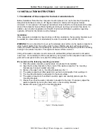
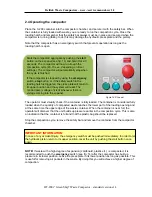
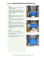
The 3 phase main el-supply is connected to the connection terminals 1, 2 & 3 as showed in
fig. 3. After the connection of the el- wires, it is crucial to check the direction of rotation of the el-
motor. If the connection is done correct, the el-motor will turn in the same direction as the arrow
indicates, counter clockwise (see fig. 4). If the el-motor turns in the opposite direction the phases
are wrongly connected. The motor will start, but the hydraulic system will not function properly.
Please swap wires of terminals 1, 2 & 3 in order to correct this.
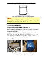
1.4 Changing the electric configuration
Normally, the waste compactor is configured for either
220V
or
380~440VAC
(480VAC with
special transformer). However, the electric configurations can be changed afterwards from one
to the other option. This procedure must always be performed by a qualified electrician.
WARNING!
Be sure to completely disconnect the el-supply to the waste compactor before rewiring starts.
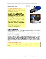
Two important procedures must then be performed:
1. The el-motor must be rewired from ”Y” (440V) to
”
∆
”
(220V) configuration or vice versa,
by rearranging the jumpers in the junction box on top of the el-motor. See also diagram
in chapter 5, section 6.
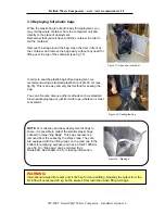
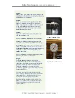
Remove the four screws in the lid on top of the el-motor and remove the lid completely
(see fig. 5). Arrange the jumpers according to the selected voltage.
(”Y” (440V) or ”
∆
” (220V) and diagram in chapter 5, section 6.
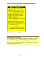
2. The connections for the transformer for 380-440V voltages must be checked and
reconfigured if necessary before el-supply is connected again (see fig. 6).
The transformer is located inside the el-panel. All components in the el-panel are running
on 220V only. The transformer is used for transforming input voltages of 380~440V
(480V) down to 220V for the components in the el-panel.
Figure 5. Y- ”Star” configuration
Figure 6. Transformer bypass


