background image

7.3 Pair

7.3.1 Introduction

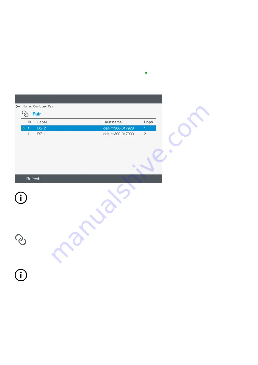
The display unit must be paired to a controller found in the DEIF network. Once the display unit has been paired to a controller, the
display unit always finds the controller even if the display unit power has been turned off.

You can also re-pair the display unit with any controller found in the DEIF network.

The current paired controller (if already paired) is marked with a green dot 

.

Figure 7.1

Example of pair screen

INFO

The pair screen shows automatically if the previously paired controller cannot be found. In this situation, either troubleshoot
the connection to the controller or select an alternative controller from the list. The screen continues to search for the
controller in the background until it is found or an alternative has been selected.

7.3.2 View or configure pair

View or configure the controller paired to the display unit under 

Configure > Pair

.

You can pair or re-pair the display unit to a controller shown in the list.

INFO

When pairing to a new controller, the display unit automatically restarts.

1. Select 

Configure

, from the 

Home

 menu.

2. Select 

Pair

 to view or configure the controller that the display unit is paired with.

OPERATOR'S MANUAL 4189341099G UK 

Page 38 of 130

Содержание PPU 300

Страница 1: ...OPERATOR S MANUAL Paralleling and Protection Unit PPU 300 DEIF A S Frisenborgvej 33 DK 7800 Skive Tel 45 9614 9614 Fax 45 9614 9615 info deif com www deif com Document no 4189341099G ...

Страница 2: ...ts 9 2 2 2 Operator information messages 11 3 Controller equipment 3 1 Display unit 15 3 1 1 Display unit DU 300 layout 15 3 1 2 Display unit DU 300 options 15 3 1 3 Display unit LEDs and push buttons 17 3 1 4 Display unit option LEDs and push buttons 19 4 Operating the controller 4 1 Introduction 21 4 1 1 About the operator actions 21 4 2 Basic actions 21 4 2 1 Changing modes 21 4 2 2 Starting th...

Страница 3: ... configure hardware module I O terminals 49 7 6 5 I O terminal settings 50 7 7 Digital input DI 51 7 7 1 Configure I O name 51 7 7 2 Configure function s 52 7 7 3 Configure alarm s 54 7 8 Digital output DO 57 7 8 1 Configure I O name 57 7 8 2 View or configure I O relay 57 7 8 3 Configure function s 58 7 8 4 Configure alarm s 61 7 9 Analogue input AI 62 7 9 1 Introduction to analogue inputs 62 7 9...

Страница 4: ...estore controller 105 10 1 3 Delete backups 106 10 2 Backup 107 10 2 1 About Backup 107 10 2 2 Create backups 107 10 3 Regulator status 108 10 3 1 About Regulator status 108 10 3 2 View Regulator status screens 108 10 4 Units 109 10 4 1 About units 109 10 4 2 View or configure unit settings 109 10 5 Communication 110 10 5 1 About communication 110 10 5 2 View or configure controller communication ...

Страница 5: ...1 Introduction to SWBD control 123 13 2 2 Troubleshooting the system under SWBD control 123 13 3 Troubleshooting alarms 124 13 3 1 Troubleshooting alarms 124 13 4 Network and communication 124 13 4 1 DEIF network redundancy broken 124 13 4 2 DL mode 125 14 Maintenance 14 1 PCM3 1 internal battery 126 14 1 1 Changing the battery 126 15 End of life 15 1 Disposal of WEEE 128 15 1 1 Disposal of waste ...

Страница 6: ...rvice and support options on the DEIF website www deif com You can also find contact details on the DEIF website You have the following options if you need technical support Help The display unit includes context sensitive help Technical documentation Download all the product technical documentation from the DEIF website www deif com documentation Training DEIF regularly offers training courses at...

Страница 7: ...r trips a breaker because of over current The operator then manually that is not using the controller closes the breaker while the Over current alarm is still latched If another over current situation arises the controller does not trip the breaker again The controller regards the original Over current latched alarm as still active and it does not provide protection 1 3 Legal information 1 3 1 Thi...

Страница 8: ...1 3 4 Copyright Copyright DEIF A S 2020 All rights reserved OPERATOR S MANUAL 4189341099G UK Page 8 of 130 ...

Страница 9: ... if an alarm condition arises the controller activates the alarm action Display unit screen The operator can monitor system operation on the display unit screen The operator can also use the soft key buttons and the display unit screen to log into the controller The operator can then see the alarm lists and logs and acknowledge and unlatch alarms The operator can also see and or change the control...

Страница 10: ...point for de loading the breaker Dividing section The controller is broadcasting set points for de loading the breaker Engine stopping The genset is being stopped Fixed power The genset is running and is being regulated to a fixed power Fixed frequency The genset is running and is being regulated using fixed frequency regulation Frequency droop The genset is running and is being regulated using fr...

Страница 11: ...r is open Start prepare s The remaining time in seconds for the genset to prepare to start Stop coil activated s The remaining time in seconds before the genset shuts down Switchboard control The controller is under switchboard control Synchronising GB The controller is synchronising the genset to the busbar frequency and voltage to close the generator breaker Synchronising sections The controller...

Страница 12: ...er operator actions cannot be performed from the controller interfaces Change of synchronisation settings not possible in SWBD The input from the static synchronisation or dynamic synchronisation digital input is ignored when the controller is under switchboard control Dynamic synchronisation activated The digital input is activated The controller will use dynamic synchronisation Dynamic synchroni...

Страница 13: ...sing GB open and stop not possible in SWBD While the controller is under switchboard control operator actions cannot be performed from the controller interfaces GB open cancelled The GB open was cancelled by a GB close command GB open not possible in SWBD While the controller is under switchboard control operator actions cannot be performed from the controller interfaces Mode change locked It is n...

Страница 14: ...d SGB open not possible in SWBD While the controller is under switchboard controller operator actions cannot be performed from the controller interfaces Start enable not activated The genset cannot start because Start enable is not activated Static synchronisation activated The digital input is activated The controller will use static synchronisation Static synchronisation deactivated The digital ...

Страница 15: ... 2 Bottom strip Blank bottom strip shown The LEDs and push buttons for the top part are the same for all controller types The LEDs push buttons and picture on the bottom strip vary according to the controller type 3 1 2 Display unit DU 300 options The bottom strip of the front of the display unit can include LEDs that show the equipment and controller status as well as push buttons for operator ac...

Страница 16: ...on LEDs LEDs for generator and busbar V Hz LED for breaker status No display unit push buttons Control mode REMOTE mode only Remote commands start sequences from Modbus digital inputs PICUS CustomLogic and or CODESYS Display unit with breaker push buttons Figure 3 3 Example of display unit with breaker push buttons LEDs shown in yellow Functions Display unit with breaker push buttons LEDs for gene...

Страница 17: ...splay unit push buttons for breaker open and close and genset start and stop are ignored LOCAL mode Display unit push buttons start one touch sequences Remote commands for breaker open and close and genset start and stop are ignored 3 1 3 Display unit LEDs and push buttons The top part of the front of the display unit is the same for all controller types It includes LEDs that show the controller s...

Страница 18: ...Red constant Alarm s active and all alarms acknowledged Red flashing Unacknowledged alarm s Yellow Unlatched alarms can be reset when no other alarms require action Yellow flashing Unacknowledged latched alarms Green flashing Only unacknowledged alarm s where the alarm condition has cleared Green constant No alarms INFO The display unit LEDs show the status of the controller and not the status of ...

Страница 19: ...cy are measurable but not OK The controller cannot close the breaker OFF The generator voltage is too low to measure 3 Breaker Green The breaker is closed Yellow The breaker spring is charging only applies to a compact breaker Yellow flashing The controller is synchronising or de loading the breaker Red The controller tripped the breaker and the trip alarm is unacknowledged and or the alarm condit...

Страница 20: ...trol The controller ignores the input from this push button 3 Close breaker LOCAL mode or Switchboard control The controller starts the breaker close sequence REMOTE mode or Switchboard control The controller ignores the input from this push button 4 Open breaker LOCAL mode The controller starts the breaker open sequence REMOTE mode or Switchboard control The controller ignores the input from this...

Страница 21: ...ntrol you must first change to REMOTE LOCAL mode LOCAL To change to LOCAL mode from REMOTE mode 1 Operator action Press to select LOCAL mode System response The LED next to is green when the controller is in LOCAL mode You cannot change from switchboard control to LOCAL mode using the display unit push buttons If the controller is under switchboard control you must first change to REMOTE LOCAL mod...

Страница 22: ... press to open the breaker before stopping the engine See Opening the generator breaker for more information To stop the engine 1 Operator action To stop the engine with a cooldown time press once System response The controller stops the engine after the cooldown time System response If the engine does not stop the controller activates an alarm 2 Operator action Press again to skip the cooldown ti...

Страница 23: ...he controller is under switchboard control the display unit bottom strip push buttons are disabled The generator breaker can only be closed using the switchboard 4 2 5 Opening the generator breaker Mode Procedure REMOTE When the controller is in REMOTE mode the generator breaker is opened based on a remote signal for example from a PLC LOCAL To open the generator breaker 1 Operator action Press to...

Страница 24: ...tus bar icons Icons represent certain active features or functions See Using the display unit Introduction About the status bar in this chapter for more information 3 Path Path for the currently viewed menu or feature 4 Menu or page The menu or page currently being viewed 5 Selection bar Soft keys used for selection or options depending on the page being viewed See Using the display unit Introduct...

Страница 25: ... controller See Overview of the controller Operator messages Controller status texts for more information 2 Active alarm s At least one active alarm is present This can include latched alarms 3 User The display unit has a user logged on 4 Page number Shows the Live data page number only on the Live data screen OPERATOR S MANUAL 4189341099G UK Page 25 of 130 ...

Страница 26: ...file however this only provides limited access or features More information See Other functions in the Designer s handbook for more information regarding groups and users 6 2 Log on 6 2 1 Log on to controller Log on to the controller under Log on INFO You do not need to log on to the controller to view the Live data information or access Alarms Figure 6 1 Example log on screen Log on to controller...

Страница 27: ...and layouts 5 Select Log on Log on If the password is correct you are logged on as the new user The Home menu is then displayed on screen A logged on icon is shown in the top right of the display 1 If the password is entered in incorrectly the following message is displayed The message automatically closes after a couple of seconds or you can press OK To attempt to log on again continue again from...

Страница 28: ...Language 6 4 1 Introduction The controller can be configured with more languages by installing different language files You can change the displayed language by using the language option By changing the display language all of the menus and options become translated automatically 6 4 2 Language restrictions CAUTION The language feature is ONLY available if both the controller and the display unit ...

Страница 29: ...lled languages are shown on the display 3 Highlight the required language 4 Press OK to change the displayed language A confirmation is shown on the display Press OK to change the displayed language Press Back to cancel the change and return to the previous screen OPERATOR S MANUAL 4189341099G UK Page 29 of 130 ...

Страница 30: ...n screen is refreshed for example by scrolling up and down in the menu Change time When a time server is configured the Time setting is greyed out and you are not able to manually change the time 1 To change the time highlight Time and press OK INFO If you are not already logged on you are prompted to do so To change the highlighted selection press Up to increase the value or Down to decrease the ...

Страница 31: ...ighted selection press Up to increase the value or Down to decrease the value To move to the next selection press OK or select Left or Right to move to the previous or next selection 2 You can now either Set the new date by selecting Write Cancel the date change by pressing Back Change time zone 1 To change the time zone highlight Time zone and press OK INFO If you are not already logged on you ar...

Страница 32: ... time zone change by pressing Back Change time format 1 To change the time format highlight Time format and press OK INFO If you are not already logged on you are prompted to do so 2 Highlight the time format you wish to select by pressing Up or Down Selecting the 12 hour clock format will display the time as hh mm ss AM PM 3 You can now either Set the time format by selecting Write Cancel the tim...

Страница 33: ...at change by pressing Back 7 2 View design 7 2 1 View or configure View Design View or configure the controller Live data views under Configure View design From this screen you can Add a new view Delete a view Rename a view Move the views Set the displayed range INFO Use View design to view or configure the Live data screens for the paired controller Add view 1 To add a new view select Add Add A l...

Страница 34: ...ssing OK You can now select and configure the measurements shown based on the template 4 Highlight the measurement to configure by pressing Up or Down 5 Select the measurement to configure by pressing OK A list of available measurements is displayed OPERATOR S MANUAL 4189341099G UK Page 34 of 130 ...

Страница 35: ...NFO This view is available on the Live data pages Delete view 1 Highlight the view to delete by pressing Up or Down 2 Delete the view by pressing Delete Delete A confirmation is shown on the display 3 Confirm deleting the view by pressing OK Or you can cancel deleting the view by pressing Back Rename view 1 Highlight the view to rename by pressing Up or Down 2 Rename the view by pressing Rename Re...

Страница 36: ...w and write a blank name to the controller That is a name that contains no characters and no spaces Move view 1 Move the views by pressing Move 2 Highlight the view to move by pressing Up or Down 3 Select the view by pressing OK 4 Move the view up or down by pressing Up or Down OPERATOR S MANUAL 4189341099G UK Page 36 of 130 ...

Страница 37: ... press OK 2 Highlight the element that you want to change by pressing Up or Down 3 Select Scale to change the range Press Up or Down to highlight the minimum or maximum value Press OK to open the virtual keyboard to change the value 4 To confirm the range select Write To restore the default range select Clear Clear To cancel your changes and return to the previous screen press Back OPERATOR S MANU...

Страница 38: ...red controller cannot be found In this situation either troubleshoot the connection to the controller or select an alternative controller from the list The screen continues to search for the controller in the background until it is found or an alternative has been selected 7 3 2 View or configure pair View or configure the controller paired to the display unit under Configure Pair You can pair or ...

Страница 39: ...shown indicate how close the controller may be to the display unit 1 hop typically indicates that the controller is directly plugged in to the display unit 3 Highlight the controller you wish to pair with by pressing Up or Down INFO The current paired controller if already paired is marked with a green dot 4 Select the controller by pressing OK A confirmation is displayed on screen OPERATOR S MANU...

Страница 40: ...lete 7 4 Counters 7 4 1 View or configure counters View or configure counters under Configure Counters Here you can view set or reset the counter information INFO You must be logged on with a user with the necessary permission to change the counter information If you are not logged on you are asked if you wish to log on View the counter information 1 Scroll the counter information by pressing Up o...

Страница 41: ...ng Up or Down to move and OK to expand or collapse groups 2 With the counter highlighted select Reset Reset INFO If you are not already logged on you are prompted to do so A confirmation is displayed on screen 3 You can now either Confirm the reset by pressing OK OPERATOR S MANUAL 4189341099G UK Page 41 of 130 ...

Страница 42: ...g Up or Down to move and OK to expand or collapse groups 2 With the counter highlighted press OK INFO If you are not already logged on you are prompted to do so The virtual keyboard is shown on the display 3 Enter the required counter value and select Write A confirmation is displayed on screen OPERATOR S MANUAL 4189341099G UK Page 42 of 130 ...

Страница 43: ...ettings The parameters are organised into categories and groups Category Group Parameter s Configure parameters Figure 7 2 Example parameter categories To configure the parameters perform the following steps 1 Select Configure from the Home menu 2 Select Parameters to view the controller parameter categories The parameter categories shown depend on the type of controller or whether the associated ...

Страница 44: ...is text or a value pressing OK displays the virtual keyboard to alter the setting The parameter settings minimum maximum and default are also shown Use the Virtual keyboard to make the required changes To confirm the setting select Write If the setting is a curve Highlight Setup by pressing Up or Down Select the option by pressing OK The curve graph is now displayed See View or configure curve in ...

Страница 45: ...move to remove a highlighted set of coordinates INFO Remove Remove is NOT shown in there are only 4 coordinate sets as this is the minimum required for the curve setting 5 Select Column Column to change the highlighted column between X and Y as necessary 6 To edit a coordinate a Select OK The virtual keyboard is shown on the display Use the virtual keyboard to edit the setting as necessary b Selec...

Страница 46: ...displayed on the screen 2 Select Edit Edit to edit the curve settings See section above 3 Select Write to write the curve settings to the controller Select Back to return to the parameter screen Engine derate example 1 The function Engine Derate 1 temperature is first assigned to an analogue input AI 2 The derate curve Engine Power derate 1 now appears on the parameters list OPERATOR S MANUAL 4189...

Страница 47: ... Select Power derate 1 Select Setup to display the derate curve Configure the curve settings as stated above OPERATOR S MANUAL 4189341099G UK Page 47 of 130 ...

Страница 48: ...if it is already assigned to another analogue input AI The selected function s type can either be Analogue input function s Analogue functions or Digital input function s Supervised binary input CAUTION You cannot use both analogue AND digital functions on the same terminal Analogue output AO Functions allowed 1 function on the same input terminal Restrictions The function must be selected before ...

Страница 49: ... module INFO Basic details about the available I Os on the module are shown at the right Selecting a hardware module To select the hardware module perform the following steps 1 Optional To move between the controller and extension unit select Up or Down by pressing Select the controller or extension unit by pressing OK This step is only required if there are extension units connected to the contro...

Страница 50: ... DO Digital output AI Analogue input AO Analogue output PWM Pulse width modulation View or configure terminal settings 1 Highlight the required terminal by pressing Up or Down 2 Select the highlighted terminal by pressing OK Details of the terminal settings are displayed on the screen 7 6 5 I O terminal settings After selecting the hardware module and the required terminal the details of the termi...

Страница 51: ...e you have selected Option Notes DI DO AI AO PWM I O name Configure I O name Relay Configure relay Sensor Configure analogue input settings Output setup Configure analogue output or PWM settings Functions Assign function s to the I O Alarm Assign alarm s to the I O 7 7 Digital input DI 7 7 1 Configure I O name To rename the input or output name 1 Select I O name I O name The virtual keyboard is di...

Страница 52: ... available are organised in categories and groups which are similar to a tree structure view Selecting a function 1 Select Functions Functions The function groups are shown on the display 2 Highlight a category or group by pressing Up or Down OPERATOR S MANUAL 4189341099G UK Page 52 of 130 ...

Страница 53: ...oup is shown simply repeat step 1 to locate and open the required group Example showing a further group The Function list shows the available functions for selection Configure functions 1 To select the functions for the terminal OPERATOR S MANUAL 4189341099G UK Page 53 of 130 ...

Страница 54: ...the setting s to the controller select Write This only applies to the selected functions and does not apply to other I O change s 7 7 3 Configure alarm s Create a new digital custom alarm To create a new alarm simply edit one of the available Digital custom alarms listed INFO It is recommended to give your created alarms a new descriptive name for easier reference OPERATOR S MANUAL 4189341099G UK ...

Страница 55: ... is Enable or Not enabled pressing OK toggles either Enable or Not enabled Enabled settings are marked with a solid box If the setting is text or a value pressing OK displays the virtual keyboard to alter the setting Make the required changes using the virtual keyboard To confirm the changes select Next Next If the setting is a selection pressing OK displays an available list of selection options ...

Страница 56: ...m alarm 1 Highlight the required custom alarm by pressing Up or Down CAUTION Editing an existing custom alarm changes the alarm settings for ALL input terminals using the same alarm 2 Select Edit Edit Details of the alarm settings are shown on the display for you to configure a Highlight the required alarm setting by pressing Up or Down b To change the setting press OK If the setting is Enable or ...

Страница 57: ...controller select Write This only saves the selected alarm s and their settings to the controller It does not save other I O settings Clear all enabled alarm s 1 To clear all the selected alarms select Clear Clear 2 To save the new setting to the controller select Write This only saves the selected alarm s and their settings to the controller It does not save other I O settings 7 8 Digital output ...

Страница 58: ...ther Energised or De energised The current setting is shown on the display 2 You can set the relay as either Energised or De energised 3 To set as Energise select Energised Energised 4 To set as De energise select De energised De energised 5 To save the setting to the controller select Write You are returned to the terminal screen 7 8 3 Configure function s The functions available are organised in...

Страница 59: ...ighlighted category or group by pressing OK If a further group is shown simply repeat step 1 to locate and open the required group Example showing a further group The Function list shows the available functions for selection OPERATOR S MANUAL 4189341099G UK Page 59 of 130 ...

Страница 60: ...ect the functions for the terminal Highlight the required function by pressing Up or Down Enable the highlighted function by pressing OK Selected function s are shown with a solid box OPERATOR S MANUAL 4189341099G UK Page 60 of 130 ...

Страница 61: ...th an alarm the display will automatically jump to the alarm settings You can if required use Back to return to the alarm selection screen Selecting an alarm 1 Highlight a category or group by pressing Up or Down 2 Select the highlighted category or group by pressing OK A further group may be shown or the alarm list to select the actual alarm s If a further group is shown simply repeat step 1 to l...

Страница 62: ...r digital functions To detect sensor failure As the basis for one or more alarms For each analogue input use the table below shows which pages in the analogue input view you must configure Table 7 1 Configuration for the uses of an analogue input Use Functions Sensor setup Alarms Analogue function s Digital function s Sensor failure Alarm s Note represents required configuration represents optiona...

Страница 63: ... virtual keyboard is displayed on screen to edit the I O name 2 Enter the required I O name and select Write 7 9 4 Configure function s The functions available are organised in categories and groups which are similar to a tree structure view For analogue inputs AI you can select either Analogue Analogue function s Digital Supervised binary input function s CAUTION When using Supervised binary inpu...

Страница 64: ...ing OK The display unit will show the function list or another function group If another function group is shown repeat step 3 to open the required group 5 Highlight a function by pressing Up or Down 6 Enable the highlighted function by pressing OK Selected function s are shown with a solid box INFO You can add further functions to the same input provided they have the same unit of measure 7 To cl...

Страница 65: ...or clear function s 1 You can edit the selected function s by pressing OK The function is now shown on the screen 2 To clear all the Enabled function s select Clear Clear 3 To save the settings to the controller select Write INFO This only applies to the selected functions and does not apply to other I O change s The terminal s settings are now shown on the screen OPERATOR S MANUAL 4189341099G UK ...

Страница 66: ...2 Select and enable the alarm by pressing OK Enabled alarm s are shown with a solid box 3 Select Edit Edit Details of the alarm settings are shown on the display for you to configure a Highlight the required alarm setting by pressing Up or Down b To change the setting press OK If the setting is Enable or Not enabled pressing OK toggles either Enable or Not enabled Enabled settings are marked with ...

Страница 67: ...ssing OK To confirm the setting select Next Next c Once you have made all the required changes to the alarm settings select Write This saves the alarm setting to the controller This does not save any other settings The list of available alarms is shown again on the display Select an existing analogue custom alarm You can use or edit an existing Analogue custom alarm 1 Highlight the required custom...

Страница 68: ...ite This saves the alarm setting to the controller This does not save any other settings The list of available alarms is shown again on the display 3 To save the new setting to the controller select Write This only saves the selected alarm s and their settings to the controller It does not save other I O settings Clear all enabled alarm s 1 To clear all the selected alarms select Clear Clear 2 To ...

Страница 69: ...required output type by pressing Up or Down 3 Select the highlighted output type by pressing OK The selected output type is marked with a solid box 4 To proceed to the next stage select Next Next OPERATOR S MANUAL 4189341099G UK Page 69 of 130 ...

Страница 70: ...f you alter the settings for a curve this will apply to all other I O terminals where the curve has been used Select a pre configured curve INFO If available you can select a pre configured curve for example VDO 5 Details for the curve are shown on the right and you cannot modify a pre configured curve 1 Highlight the pre configured curve by pressing Up or Down 2 Select the pre configured curve by...

Страница 71: ...ings to the controller select Write This only saves the selected settings to the controller It does not save other I O settings Select a new custom curve 1 Highlight an unused custom curve by pressing Up or Down OPERATOR S MANUAL 4189341099G UK Page 71 of 130 ...

Страница 72: ...g by pressing OK If the setting is text or a value pressing OK displays the virtual keyboard to change the setting For example the name of the curve To confirm the setting select Next Next If the setting is a selection pressing OK displays an available list of selection options For example the y axis units OPERATOR S MANUAL 4189341099G UK Page 72 of 130 ...

Страница 73: ...g OK displays the coordinate options CAUTION Configure the y axis units y axis minimum and y axis maximum BEFORE attempting to configure the x y coordinates CAUTION A valid curve must contain a minimum of 2 sets of coordinates a Add coordinates a To add a set of x y coordinates select Add Add The Virtual keyboard is shown on the display OPERATOR S MANUAL 4189341099G UK Page 73 of 130 ...

Страница 74: ...rd This must be between the minimum and maximum values shown Select Next Next c Enter the y axis coordinate using the Virtual keyboard This must be between the minimum and maximum values shown Select Next Next OPERATOR S MANUAL 4189341099G UK Page 74 of 130 ...

Страница 75: ...hen you have added all the coordinates you require press Back to return to the curve settings b Edit coordinates a Highlight the coordinate to edit by pressing Up or Down b Select Edit Edit The Virtual keyboard is shown on the display for the x coordinate OPERATOR S MANUAL 4189341099G UK Page 75 of 130 ...

Страница 76: ...coordinate using the Virtual keyboard Select Next Next d Edit the y coordinate using the Virtual keyboard Select Next Next e The x y coordinates are updated in the list OPERATOR S MANUAL 4189341099G UK Page 76 of 130 ...

Страница 77: ... require press Back to return to the curve settings c Remove coordinates a Highlight the coordinate to remove by pressing Up or Down b Select Remove Remove The coordinate is removed from the coordinate list OPERATOR S MANUAL 4189341099G UK Page 77 of 130 ...

Страница 78: ...ve settings 6 To save the curve to the controller select Write The custom curve is updated in the list 7 Highlight the custom curve by pressing Up or Down 8 Select the custom curve pressing OK The selected custom curve is marked with a solid box OPERATOR S MANUAL 4189341099G UK Page 78 of 130 ...

Страница 79: ...erminal s for an Analogue output AO to be used 2 If required select the function input x axis 3 Configure the Output setup settings and curve y axis 4 Write the Output setup settings to the controller 7 10 2 Configure I O name To rename the input or output name 1 Select I O name I O name The virtual keyboard is displayed on screen to edit the I O name 2 Enter the required I O name and select Write...

Страница 80: ...ctual function If another group is shown repeat step 1 to locate and open the required group 3 Highlight the required function by pressing Up or Down 4 Enable the highlighted function by pressing OK Selected function is shown with a solid box 5 To clear all the Enabled function select Clear Clear 6 To save the settings to the controller select Write INFO This only applies to the selected function ...

Страница 81: ...O This only applies to the selected functions and does not apply to other I O change s The terminal s settings are now shown on the screen 7 10 4 View or configure analogue output AO or pulse width modulation PWM INFO Configure the function before configuring the output setup More information See Analogue output AO Pulse Width Modulation PWM Configure function s for more information OPERATOR S MAN...

Страница 82: ...ist of available output types are shown on the display INFO This is the y axis 2 Highlight the required output type by pressing Up or Down 3 Select the highlighted output type by pressing OK The selected output type is marked with a solid box OPERATOR S MANUAL 4189341099G UK Page 82 of 130 ...

Страница 83: ...ve Select or edit an existing custom curve CAUTION You can reuse any previously created custom curve on any terminal s However the configuration settings are the same across all the other I O terminals If you alter the settings for the curve this will apply to all other I O terminals where the curve has been used OPERATOR S MANUAL 4189341099G UK Page 83 of 130 ...

Страница 84: ...fined curve 1 Highlight the pre configured curve by pressing Up or Down 2 Select the pre configured curve by pressing OK The selected curve is shown with a solid box To remove the selection press OK again 3 To save the settings to the controller select Write This only saves the selected settings to the controller It does not save other I O settings OPERATOR S MANUAL 4189341099G UK Page 84 of 130 ...

Страница 85: ... Highlight an unused custom curve by pressing Up or Down 2 Select Edit Edit Details of the curve settings are shown on the display 3 Highlight a curve setting by pressing Up or Down OPERATOR S MANUAL 4189341099G UK Page 85 of 130 ...

Страница 86: ...select Next Next If the setting is a selection pressing OK displays an available list of selection options For example the x axis units Highlight the option required by pressing Up or Down Select or unselect the option by pressing OK To confirm the setting select Next Next If the setting is the x y coordinates pressing OK displays the coordinate options OPERATOR S MANUAL 4189341099G UK Page 86 of ...

Страница 87: ...alid curve must contain a minimum of 2 sets of coordinates a Add coordinates a To add a set of x y coordinates select Add Add The Virtual keyboard is shown on the display b Enter the x axis coordinate using the Virtual keyboard This must be between the minimum and maximum values shown OPERATOR S MANUAL 4189341099G UK Page 87 of 130 ...

Страница 88: ... using the Virtual keyboard This must be between the minimum and maximum values shown Select Next Next d The x y coordinates are added to the list e You can add a maximum of 30 coordinates to the curve OPERATOR S MANUAL 4189341099G UK Page 88 of 130 ...

Страница 89: ...the curve settings b Edit coordinates a Highlight the coordinate to edit by pressing Up or Down b Select Edit Edit The Virtual keyboard is shown on the display for the x coordinate c Edit the x coordinate using the Virtual keyboard OPERATOR S MANUAL 4189341099G UK Page 89 of 130 ...

Страница 90: ...Next e The x y coordinates are updated in the list f When you have added edited all the coordinates you require press Back to return to the curve settings c Remove coordinates a Highlight the coordinate to remove by pressing Up or Down OPERATOR S MANUAL 4189341099G UK Page 90 of 130 ...

Страница 91: ...n you have added edited all the coordinates you require press Back to return to the curve settings The custom settings are updated in the list 6 Return to the curve selection by selecting Write The custom curve is updated in the list OPERATOR S MANUAL 4189341099G UK Page 91 of 130 ...

Страница 92: ... Up or Down 8 Select the custom curve pressing OK The selected custom curve is marked with a solid box 9 To save the settings to the controller select Write You are returned to the terminals page OPERATOR S MANUAL 4189341099G UK Page 92 of 130 ...

Страница 93: ...alarm action can be deactivated Figure 8 1 Example display unit 1 2 No Item Notes 1 Alarm indicator LED Displays the current alarm situation for the system 2 Horn output silence push button Used to silence the horn output if configured Alarm indicator LED The alarm indicator shows the current alarm situation for the system Indicator LED Notes Red flashing Unacknowledged alarm s Red constant Active...

Страница 94: ...tion Acknowledge Notes or Active Active Unacknowledged Alarm condition is occurring Alarm action is active Alarm requires acknowledgement Alarm requires action to clear the alarm condition or Active Active Acknowledged Alarm condition is occurring Alarm action is active Alarm is acknowledged Alarm requires action to clear the alarm condition or Inactive Active Unacknowledged Alarm condition has cl...

Страница 95: ... typically where the Set point has been exceeded Note Alarm action protection is the configured action taken to protect the situation When active this action occurs in the controller For example the alarm action could be Trip breaker More information See Alarms Alarm handling in the Designer s handbook for more information about alarm handling Test alarms A green yellow if alarm is highlighted ala...

Страница 96: ...hecked and may become active again if the Alarm condition remains active Out of service Most alarms can be removed from service No period of time needs to be given The system does not automatically return the alarm to service and this requires action to do so INFO Some alarms can be inhibited from occurring depending on the designer s configuration of the system More information See Alarms Alarm h...

Страница 97: ...e alarm list 5 If the alarm condition clears and the alarm has a Latch configured The acknowledged alarm remains on the alarm list and requires a reset before the alarm is removed 6 If the alarm condition remains active The acknowledged alarm remains on the alarm list but is now marked as acknowledged Until the latched alarm is reset the alarm action protection remains active even though the alarm...

Страница 98: ...hes INFO Resetting clears all alarm latches for all the latched alarms where the Alarm condition has cleared To reset all cleared alarm latches perform the following steps 1 Select Alarms to view the alarm list 2 Select Reset latches Reset latches 3 All alarm latches that can be reset are reset 8 2 5 Shelve alarm s Most alarms on the alarm display can be shelved for a given period of time if requi...

Страница 99: ...TION Marking alarms as Out of service is useful during commissioning or service It is not recommended to mark alarms Out of service without good reasoning as the alarm protection remains inactive while the alarm is marked as Out of service Remove an alarm from service To remove an alarm from service perform the following steps 1 Select Alarms to view the alarm list 2 Highlight the alarm to remove ...

Страница 100: ... here Reviewing Live data To view the different Live data screens perform the following steps 1 Select Live data to view the current operating information 2 Scroll through the screens by pressing Up or Down Changing Live data display if applicable Some screens in the Live data display can be changed to view alternative information Figure 9 1 Example Live data screen To cycle through the different ...

Страница 101: ...9 2 2 Live data counters View counters under Live data Live data also shows basic counter information from the controller Figure 9 2 Example PPU counters Table 9 1 PPU Live data counters Counter Unit Active energy export kWh Total running hours h Total running minutes min GB trips OPERATOR S MANUAL 4189341099G UK Page 101 of 130 ...

Страница 102: ... A 3 Generator L1 L2 voltage V AC 4 Generator L1 frequency HZ INFO Selectable display Shows 1 Busbar L1 L2 voltage V AC 2 Busbar L1 frequency Hz Shows 1 Generator active power total kW 2 Generator reactive power total kvar 3 Generator apparent power kVA 4 Generator power factor OPERATOR S MANUAL 4189341099G UK Page 102 of 130 ...

Страница 103: ...ator L2 L3 voltage V AC 3 Generator L3 L1 voltage V AC 4 Generator L1 frequency Hz Shows 1 Busbar L1 L2 voltage V AC 2 Busbar L2 L3 voltage V AC 3 Busbar L3 L1 voltage V AC 4 Busbar L1 frequency Hz Shows 1 Generator L1 current A 2 Generator L2 current A 3 Generator L3 current A OPERATOR S MANUAL 4189341099G UK Page 103 of 130 ...

Страница 104: ...ltage V AC 2 Generator L2 L3 voltage V AC 3 Generator L3 L1 voltage V AC 4 Generator L L min voltage V AC Shows 1 MPU frequency RPM 2 Coolant water temperature C 3 Oil pressure bar Shows counters 1 Active power export kWh 2 Total running hours h 3 Total running minutes min 4 GB trips OPERATOR S MANUAL 4189341099G UK Page 104 of 130 ...

Страница 105: ... the current controller software You can see detailed information about non compatible backup files but you are not able to restore the backup file Seeing more backup information To see detailed information about a backup perform the following steps 1 Select Tools from the Home menu 2 Select Restore from the Tools menu 3 Highlight the backup that you want to see detailed information of by pressing...

Страница 106: ... procedure by pressing OK INFO If you are not already logged on you are prompted to do so 6 Select the data you want to restore a Highlight the data you want to restore using Up or Down b Select the data by pressing OK 7 You can now either Restore the data by selecting Restore Restore You are prompted to confirm that you want to restore the selected data Press OK to confirm restoring the selected ...

Страница 107: ...1 About Backup The backup page allows you to create and store backup files on the controller or the controller s SD card FAT32 INFO You can store up to 20 backups on the controller 10 2 2 Create backups Create controller backups under Tools Backups Creating backups To create a controller backup file perform the following steps 1 Select Tools from the Home menu 2 Select Backup from the Tools menu 3...

Страница 108: ...reate backup to create a backup INFO If you are not already logged on you are prompted to do so You are prompted to confirm that you want to create a backup file Press OK to create the backup Press Back to cancel creating the backup 10 3 Regulator status 10 3 1 About Regulator status The Regulator status page allows you to see the regulator status for governor and AVR GOV AVR selected regulaton mo...

Страница 109: ...AVR status AVR status on the GOV status screen to change the view to the AVR status screen 10 4 Units 10 4 1 About units The units page allows you to change the unit of measure for Temperature C Celsius or F Fahrenheit Pressure bar or psi INFO Changing a unit of measure affects various display unit screens For example Live data parameters I O curve configuration However it does not affect PICUS 10...

Страница 110: ...essing Up or Down 6 Select the unit of measure by pressing OK The selected unit of measure is shown with a solid box 7 To confirm the change select Write The setting becomes saved to the display unit You are returned to the previous screen 10 5 Communication 10 5 1 About communication Configure communication information under Tools Communication The communication page allows you to view or configu...

Страница 111: ...display unit you must also update the controller ID in the PICUS single line diagram The system can have up to 32 controllers with controller IDs in the given range IPv6 address No default Label Text No default A description label for the controller rack DNS preferred 0 0 0 0 255 255 255 255 No default DNS alternate 0 0 0 0 255 255 255 255 No default IP address mode Static Auto Auto Select Static ...

Страница 112: ... controller rack and restart the display unit DANGER For changes to communication settings to take effect all controllers and displays in the same system MUST only be powered off and powered on This must be done by authorised personnel who understand the risks involved in accessing the power supply or installation design Take extreme care in the enclosure next to the ACM terminals Ensure the contr...

Страница 113: ...f you select Static then you must give the controller a unique IPv4 address In addition some addresses in this range are reserved Figure 10 4 Display unit communication screen View or configure display unit communication settings To view or configure the display unit communication information perform the following steps 1 Select Tools from the Home menu 2 Select Communication to view the communica...

Страница 114: ...nning and in operation and that the controlled breakers are open before powering off and on the controllers and display units 10 6 Lamp test 10 6 1 Lamp test Run the Lamp test under Tools Advanced Lamp test Run lamp test To run the lamp test perform the following steps 1 Select Tools from the Home menu 2 Select Advanced from the Tools menu 3 Highlight Lamp test from the Advanced menu 4 Run the lam...

Страница 115: ... Advanced from the Tools menu 3 Select Brightness from the Advanced menu 4 Select Brightness level from the Brightness menu The currently configured brightness level is shown with a solid box 5 Highlight the required brightness level by pressing Up or Down 6 Select the brightness level by pressing OK The selected brightness level is shown with a solid box 7 To confirm the change select Write The s...

Страница 116: ... shown with a solid box 5 Highlight the required brightness time by pressing Up or Down 6 Select the brightness time by pressing OK The selected brightness time is shown with a solid box 7 To confirm the change select Write The setting becomes saved to the display unit 10 8 Permissions 10 8 1 About permissions The permissions menu allows you to do the following View the Group information View the ...

Страница 117: ... menu 4 Select Groups from the Permissions menu to view the group information Details of the groups setup on the controller are displayed on screen The group for the currently logged on user is shown with a green dot 5 Scroll through the information by pressing Up or Down 6 Further information is displayed by pressing OK on a highlighted group This includes all the associated users for the selecte...

Страница 118: ...nu 2 Select Advanced from the Tools menu 3 Select Permissions from the Advanced menu 4 Select Users from the Permissions menu to view the group information Details of the users setup on the controller are displayed on screen The user currently logged on is shown with a green dot 5 Scroll through the information by pressing Up or Down 6 Further information is displayed by pressing OK on a highlight...

Страница 119: ...t symbols Event Icon Examples General Automatic Manual System commands Breaker open Engine start System Power up Download firmware I O hardware modules installed in controller serial number software hardware version and revision Test Alarm test Lamp test Alarms Varies by alarm state Alarms occurring in the system Alarms being acknowledged by the user Alarm condition going back to normal Info Param...

Страница 120: ...der Log Reviewing log events To view a log entry perform the following steps 1 Select Log to view the event log 2 Scroll through the event log by pressing Up or Down 3 Select an event by pressing OK 4 Select either Info or Diagram by pressing Up or Down and pressing OK 5 Further details of the event are shown on the display OPERATOR S MANUAL 4189341099G UK Page 120 of 130 ...

Страница 121: ...the controller and display unit Table 12 1 About information Name Notes Controller Controller type Label Controller label PCM IP PCM IPv6 address DU IP Display unit IPv6 address Serial number Controller serial number SMD_BOM_revision PCM Surface mounted device bill of materials revision Leaded_BOM_Number PCM Leaded bill of materials number NCR_number PCM Nonconformity number INFO Actual informatio...

Страница 122: ...Figure 12 1 Example about screen Press Back to return to the Info menu To scroll the production information use Up or Down OPERATOR S MANUAL 4189341099G UK Page 122 of 130 ...

Страница 123: ...hboard control Class societies require that certain minimum protections are included in the switchboard For example there must be a synchronisation check before closing a breaker DANGER Only trained operators should operate the system under switchboard control Even though the controller protections are active the operator can create undesirable conditions during switchboard control The operator ac...

Страница 124: ...rable alarm protections Activated alarms require action to resolve the problem in the system An active alarm has an active alarm protection which is designed to protect the system and equipment More information See Alarms for more information about how alarms can be handled 13 4 Network and communication 13 4 1 DEIF network redundancy broken Alarm DEIF network redundancy broken Configuration Confi...

Страница 125: ...DEIF network connection This ensures continued operation of the system should one of the Ethernet cables become damaged or faulty 13 4 2 DL mode Description The display unit is stuck on the start screen displaying the text DL mode Possible cause s The power supply is too small to fully power the display unit resulting in an incomplete start up The Ethernet cable is loose An incomplete start up has...

Страница 126: ...supplies before replacing the battery Electrostatic precautions CAUTION Protect the hardware modules against static discharge during the battery replacement Replacing the battery 1 Disconnect all power supplies that is both PSM and if present EIM to protect the hardware modules and personnel 2 Optional Test the resistance of the wrist strap and the resistance of the wrist strap connection Do not c...

Страница 127: ...e hardware module faceplate using a screwdriver with a TX20 bit and 0 5 N m 4 4 lb in of torque INFO PCM3 1 uses a CR2430 3V battery rated for operation at 40 to 85 C 40 to 185 F This is not a standard CR2430 battery Date and time settings After the battery is replaced the date and time settings need to be reentered on the controller You can use PICUS to enter the correct date and time settings OP...

Страница 128: ...ent WEEE must therefore be disposed of properly In Europe the disposal of WEEE is governed by the WEEE directive issued by the European Parliament DEIF complies with this directive You must not dispose of WEEE as unsorted municipal waste Instead WEEE must be collected separately to minimise the load on the environment and to improve the opportunities to recycle reuse and or recover the WEEE In Eur...

Страница 129: ...us situations If the guidelines are not followed these situations could result in personal injury or damaged equipment General notes INFO This highlights general information More information This highlights where to find more information Example heading This highlights examples 16 1 2 Display unit symbols and push buttons Symbol Symbol name Notes Controller power OK Self check OK Ready for operati...

Страница 130: ... Down Back Help Genset start Genset stop Close breaker Open breaker Breaker is closed Breaker is open REMOTE mode ISO 7000 2012 symbol 1108 LOCAL mode ISO 7000 2012 symbol 1109 OPERATOR S MANUAL 4189341099G UK Page 130 of 130 ...

Отзывы: