
22
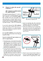
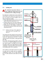
5.2 Measures to reduce the separati-
on distance "s"
(HVI Conductors installed outside
the supporting tube)
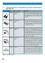
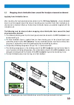
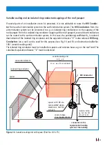
The required separation distance
“s”
can be re-
duced if the current is distributed between several
down conductors, e.g. by installing
HVI Conduc-
tors
in parallel. Since in this case magnetic inter
-
action may occur, a minimum distance must be
maintained downstream of the sealing end range/
supporting tube of the
HVI Conductors
installed
in parallel. A distance > 200 mm is recommended.
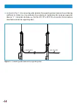
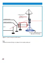
It must also be observed that
HVI Conductors
must be connected to distant points such as an
isolated ring conductor or an earth-termination
system. If these measures are taken, the current is
almost evenly distributed.
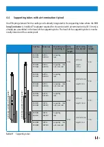
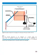
Up to four
HVI Conductors
can be connected to
the supporting tube by means of the fixing set
(Part No. 819 294).
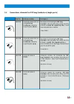
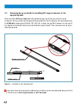
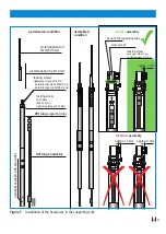
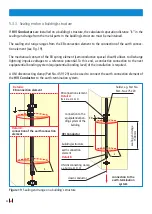
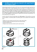
Steps for installing HVI long Conductors out-
side the supporting tube:
Â
The locking screw on the side of the head of the
supporting tube for the head piece of the
HVI
long Conductor
must be completely tightened
(see also Fig. 5, page 21). Installation may not
be possible if the screw protrudes too far from
the head of the supporting tube.
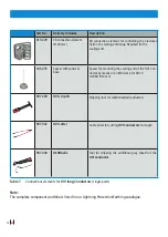
Â
Put the fixing ring with the four slotted conduc
-
tor holders for the sealing end on the top edge
of the connecting sleeve through the head of
the supporting tube or from below through the
supporting tube and pre-mount it by means of
the M8 screw. In this process, observe the posi
-
tion of the top edge of the connecting sleeve!
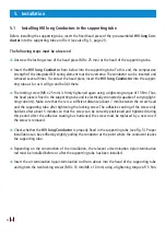
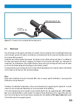
Figure 6
Step 1 for installing a
HVI long Conduc-
tor
outside the supporting tube
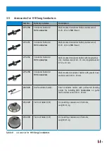
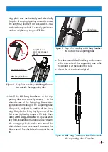
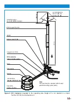
Â
Insert the connecting plate (four conductors)
through the head piece of the supporting tube
and correctly position it via the long hole.
Â
Tighten the self-locking nut with serrated bea
-
ring located on the side of the supporting tube
and properly connect the connecting plate to
the head of the supporting tube (tightening tor
-
que of 15 Nm).
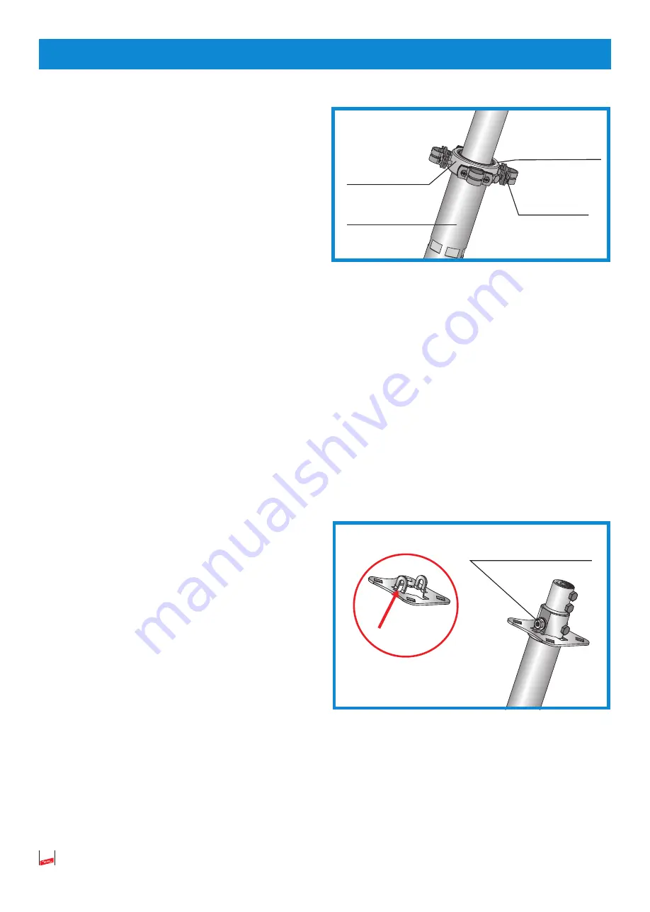
Figure 7
Step 2 for installing a
HVI long Conduc-
tor
outside the supporting tube
Â
Bring the square of the connection element of
the pre-assembled
HVI long Conductor
to be
installed outside the supporting to the connec
-
fixing ring
connecting
sleeve
M8 screw
top edge of the
connecting sleeve
Ø 60 mm
long hole
self-locking nut with
serrated bearing (15 Nm)


