background image

SI-3


U

ser
’s M
anual

7

3.  Getting Started

3.1 Introduction

The SI-3™ is a radar specifically designed to measure speeds and 
export that speed information as RS232 data via the attached 
serial cable . This allows the SI-3™ to be used for a wide range 
of applications such as Radar Speed Trailers, traffic speed data 
collection (when used with the Decatur EZ Stat™ data logger) or 
other uses where speed monitoring is desired . The SI-3™ comes 
with a Programming disk that allows the user to configure certain 
parameters of the SI-3™ for specific applications . Refer to Chapter 4 
for configuration information . Additionally, a Radar Monitor program 
is also available that allows you to display speed information on your 
computer and record that information to a text file for analysis .

3.2  Connecting the Serial Cable

The SI-3™ operates off of +12VDC and is equipped with a specialized 
DB-9 serial connector that contains provisions for powering the unit . 
When connecting the cable it is important to understand that unlike 
standard RS232 serial connectors that have no +12VDC provisions 
the SI-3's™ serial connector has two pins dedicated to B+ and ground 
for the purpose of powering the unit . Figure 3 .2 shows the pin 
arrangement . 

Figure 3.2

Front view SI-3

 Serial Connector

Pin 1 = +12VDC (power) (red wire)
Pin 2 = RS232 TX (white wire)
Pin 3 = RS232 RX (green wire)
Pin 4, 6 ,7 = N/C
Pin 5 = RS232 Ground (brown wire))
Pin 8 = Remote ON (blue wire)
Pin 9 = Ground (power) (black wire)

Содержание SI-3

Страница 1: ...User s Manual Rev 5 14 19 SI 3 System Interface 3 ...

Страница 2: ...t 14 4 6 Min Max Speed 14 4 7 Target Report 14 4 8 Target Select 15 4 9 Cosine Horizontal and Cosine Vertical 15 4 10 Update Rate 15 4 11 Hold Time and Speed Lock 15 4 12 Sensitivity 15 4 13 Serial Protocol 16 4 14 Start and Stop Output Buttons 17 4 15 Radar On Off Button 17 5 Performance Tips 18 5 1 How Radar Works 18 5 2 Interference Sources 18 5 2 1 Angular Interference Cosine Effect 18 5 2 2 F...

Страница 3: ...enna Parameters 23 8 2 Environment 23 8 3 Speed Range Parameters 23 8 4 Power Consumption 23 9 Legal Requirements 24 9 1 Documents 24 9 2 FCC Statement 25 9 3 Conditions 25 9 4 Installer Note 25 9 5 End User Note 25 10 Frequently Asked Questions FAQ 25 11 Warranty 26 12 Service Return Procedure 27 13 How To Order Additional Products 28 Appendix A SI 3 Serial Commands 29 ...

Страница 4: ...fore using the SI 3 so you can maximize the benefits of this sophisticated radar device We believe you will be pleasantly surprised by the features and advantages If you are as pleased with its performance as we think you will be ask your Decatur sales representative about other Decatur products including the Genesis line of radars the Onsite line of speed trailers dollies pole signs and the Respo...

Страница 5: ...ote 1 Safety Information All service needs should be referred back to the manufacturer WARNINGS Do not over voltage the radar it can damage the unit The SI 3 is designed to operate off of conventional 12 VDC 10 8 to 16 5 VDC from the serial cable Important Warnings Opening the SI 3 automatically voids any warranty still in effect There are no user serviceable parts inside Do not expose the SI 3 to...

Страница 6: ... document any damage Notify the freight company immediately of any damage preferably while the driver is present Record the damage on the bill of lading and keep a record of the problems or damage The package should include the following pictured items along with this User s Manual SI 3 S785 1 0 Programming USB Drive S900 34 Tuning Fork S769 127 0 Optional Programming cable ...

Страница 7: ... Monitor program is also available that allows you to display speed information on your computer and record that information to a text file for analysis 3 2 Connecting the Serial Cable The SI 3 operates off of 12VDC and is equipped with a specialized DB 9 serial connector that contains provisions for powering the unit When connecting the cable it is important to understand that unlike standard RS2...

Страница 8: ...he SI 3 has a red wire that is connected to 12 VDC and a black wire that connects to ground A regulated power supply can be used to supply the 12 VDC Once the programming software is installed on the computer then the SI 3 can be accessed and parameters changed to meet your application Refer to Chapter 4 for programming information Figure 3 3 Optional Programming Cable 3 4 Mounting Configuration T...

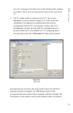
Страница 9: ...ower and Communications adapter and the PC if needed This cable is a 9 pin RS232 cable with a male connector on one end and female connector on the other SI 3 configuration USB Flash Drive S785 1 0 12V power supply 4 2 Device Configuration 1 Apply 12VDC power to the SI 3 through the programming cable Open and run the SI 3 Config configuration program the opening screen is shown in Figure 4 2a Figu...

Страница 10: ...assigned Your port assignment may be different and the port assignment can change the next time the USB to Serial adapter is plugged in Figure 4 2b Device Manager screen 2 From the Configuration Program screen select the COM port that your PC has assigned If you are connecting through the computer s serial port it will normally be Com 1 or Com 2 If you are using the USB to Serial adapter use the p...

Страница 11: ...the present configuration of the SI 3 Any changes made to the SI 3 configuration are sent and stored in non volatile memory If you turn off the SI 3 unit while the SI 3 Config program is connected just press the Disconnect button and reconnect Figure 4 2c Connected Any grayed out box such as the serial number box is for reference only and cannot be changed The OK button sends an OK command to the ...

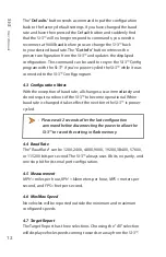
Страница 12: ...f baud rate all changes occur immediately and do not require a reboot of the SI 3 to become operational When baud rate is changed it takes effect the next time the SI 3 is power cycled Please wait 2 seconds after the last configuration command before disconnecting the power to allow the SI 3 to record the setting in flash memory 4 4 Baud Rate The Baud Rate can be 1200 2400 4800 9600 19200 38400 57...

Страница 13: ...angles between 0 and 45 degrees for maximum accuracy 4 10 Update Rate The selected message format will be sent in whatever time interval in milliseconds that you set The Update Rate can be as low as 20 milliseconds The number should be a multiple of 20 milliseconds The Update Rate and the amount of serial port activity do not affect the measurement accuracy of the SI 3 4 11 Hold Time and Speed Loc...

Страница 14: ... to use D is a direction character that is for vehicles coming towards the sign for vehicles moving away and when the direction cannot be determined S represents the displayed speed If a period is within the square brackets it is the decimal point Any zeros are sent as described and do not change with a vehicle s speed The cr signifies the end of the outgoing message The default setting is D SSS c...

Страница 15: ...s recommended that the Stop command be sent prior to any change in serial protocol if a serial protocol has been selected previously 4 14 Start and Stop Output Buttons These buttons are used to start and stop the continuously updated serial protocol Any configured Serial Protocol will resume periodic data transmission after a power cycle The Stop command is used to temporarily stop the periodic da...

Страница 16: ...tted signal 5 2 Interference Sources When properly installed and operated Doppler radar technology is extremely accurate and reliable However variations in the environment can cause situations and circumstances which can cause spurious erratic and unusually low or high speeds to display Signs that a speed is spurious can include the following characteristics A reading appears when no target is in ...

Страница 17: ... Angle Radar Figure 5 2 1 An angle between the antenna and the target causes the cosine effect The following table shows the effect that an increasing angle has on a displayed speed Horizontal Angle Degrees Actual Speed 0 1 3 5 10 15 20 30 45 60 90 Displayed speed 30 mph 30 29 29 29 29 28 28 26 21 15 0 40 mph 40 39 39 39 39 38 37 34 28 20 0 50 mph 50 49 49 49 49 48 46 43 35 25 0 60 mph 60 59 59 59...

Страница 18: ...arget speeds To correct the interference simply turn off its source 5 2 4 Feedback Interference When the radar beam is directed at computer screens streetlights and other electronic devices it can display spurious speeds To correct the interference relocate the SI 3 5 2 5 Multi Path Beam Cancellation If multi path beam cancellation occurs the target vehicle speed sporadically blinks and reappears ...

Страница 19: ...can cause the system to detect motion Obtaining a speed reading from scanning will not happen when you properly use the radar and is considered deliberate misuse of the system 5 2 8 Environmental Factors Rain Snow Environmental factors such as rain or snow can reduce the range distance at which a target can be detected However these factors will not affect accuracy ...

Страница 20: ...he tuning fork that you tapped with the narrow side facing about 3 inches directly in front of the antenna Compare the speed in the display window to the speed stamped on the fork If the difference is within 1 display unit the SI 3 is working properly Figure 6 1 Place the vibrating tuning fork about 3 inches in front of the antenna If the device does not display the expected speed contact Decatur ...

Страница 21: ... Part 15 compliant 8 1 Antenna Parameters K Band Nominal transmission frequency 24 150 GHz Nominal horizontal beamwidth 12 Polarization Linear Vertical RF Power peak 120 4 dBuV m 3m Antenna Gain Integral w 14 dBi max 8 2 Environment Ambient operating temperatures 22ºF to 158ºF 30ºC to 70ºC Maximum humidity 100 relative humidity Unit is weather proof not water proof 8 3 Speed Range Parameters Speed...

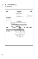
Страница 22: ...SI 3 User s Manual 22 9 Legal Requirements 9 1 Documents ...

Страница 23: ...0 cm separation is maintained between this device s antenna and all persons in order to comply with the FCC and IC RF exposure requirements 9 5 End User Note Maintain a 20 cm separation between this device s antenna and all persons during operation in order to comply with the FCC and IC RF exposure requirements 10 Frequently Asked Questions FAQ Q My SI 3 has poor range How can I remedy this A Veri...

Страница 24: ...the unit to a Decatur authorized service provider The full warranty on parts and workmanship does not include normal wear and tear crushing dropping fire impact immersion over tightening of screws damage from attempted repair or modifications by unauthorized service agents ONE YEAR WARRANTY EXCEPTION If you purchased the unit under a special buying program such as a state purchase contract etc the...

Страница 25: ...e shipped express or next day air there will be an additional charge If you are referred to a Service Provider and your product is under warranty then once your product has been received the Service Provider will investigate the problem Once they have diagnosed the problem they will repair the product and return it to you If you are referred to a Service Provider and your unit is not under warrant...

Страница 26: ...products see the Decatur Electronics Web site at www DecaturElectronics com or call the sales office at 800 428 4315 Radar Monitor The optional Radar Monitor program is designed to display speed information on a computer and record that information to a text file for analysis The program has been design to work specifically with the SI 3 For more information on the Radar Monitor contact the sales ...

Страница 27: ...wise new settings will get lost on power down Get unit ID Send ASCII i CR Radar responds back with ASCII unit ID 0 255 LF CR Get serial number Send ASCII s CR Radar responds back with ASCII unit serial number 0 65535 LF CR Set speed units conversion Send ASCII C units CR Where units 0 mph 1 kph 2 fps 3 m s Radar responds back with ASCII OK LF CR Set Max speed Send ASCII M XXX CR Where XXX max spee...

Страница 28: ...R Where XX angle degrees in ASCII format Radar responds back with ASCII OK LF CR Set hold time Send ASCII h XXXX CR Where XXXX milliseconds in ASCII format Radar responds back with ASCII OK LF CR Set update rate note radar requires a power cycle for new values to be used Send ASCII U X CR Where X 0 1 sec X 1 2 sec X 2 5 sec X 3 8 sec X 4 change only X 5 poll Radar responds back with ASCII OK LF CR...

Страница 29: ... LF CR Set baud rate Send ASCII B X CR Where X baud rate selector number in ASCII format X 0 Baud rate set to 1200 X 1 Baud rate set to 2400 X 2 Baud rate set to 4800 X 3 Baud rate set to 9600 X 4 Baud rate set to 19200 X 5 Baud rate set to 34800 X 6 Baud rate set to 57600 X 7 Baud rate set to 115200 Radar responds back with ASCII OK LF CR Note Settings will not be used until next power on cycle P...

Страница 30: ...ash Radar responds back with ASCII FACTORY DEFAULTS LF CR if successful Save configure items to FLASH Send ASCII F CR Radar responds back with ASCII OK FLASH SAVED LF CR on success or ASCII FLASH FAILURE LF CR on failure Get configure data not implemented future release Send ASCII c CR Radar responds back with list of configurable items and values 30 ...

Страница 31: ...www DecaturElectronics com 800 428 4315 ...

Отзывы: