3.
Attach the enclosure rails to each side of chassis by positioning the rails
over the keyhole tabs, and slide the rails into place. The rails are marked
“R” (right) and “L” (left) viewing from the front of the enclosure. Do not
exchange the enclosure rails. Secure each rail using seven #8-32 flat head
screws (Figure 15b).
4.
With the new replacement SS8460 in place on the lift tool carefully position
the lift tool in front of the rack (Figure 12) and raise the load plate up under
the enclosure to be removed so that the load plate is now supporting the
enclosure
. Ensure the foot brake is applied and secure in position Figure
13.
5.
Position the lift tool shelf and new replacement SS846 to the proper height
to enable alignment of enclosure rails and rack rails and slide the rear
alignment blocks on to the rack rails to align the enclosure properly with the
rack rails.
6.
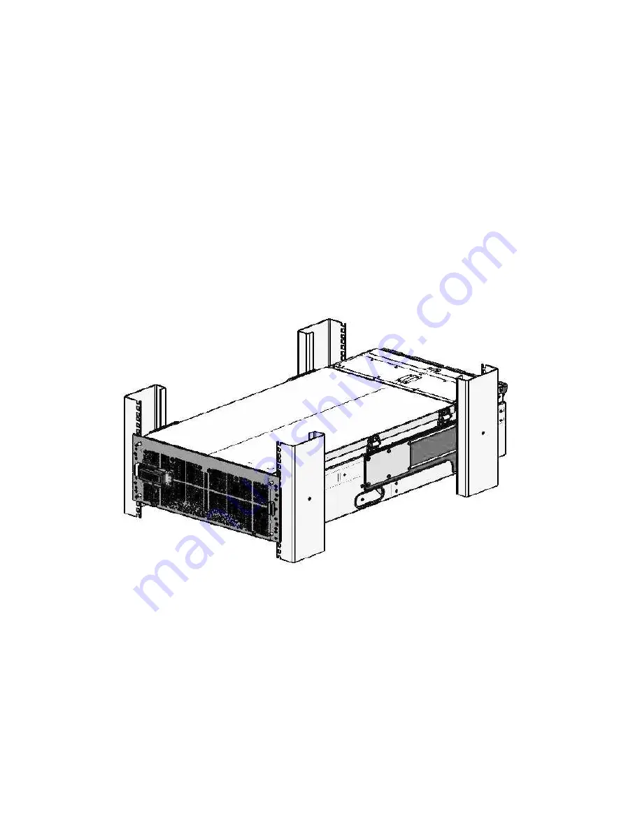
Carefully engage the enclosure rails into the rack rails and slide the
enclosure in until the enclosure rail tabs “click” into place. The SS8460
enclosure is now mounted in the rack (Figure 16).
Figure 16. Enclosure installed in Rack
7.
Carefully reinstall all drives removed in previous steps by sliding the module
into a disk slot until it contacts the baseboard and begins to engage the
handle (Figure 11). Press down on the handle until it latches which will cam
the module into place.
8.
Reconnect the SAS cables,
CMA cross bars.
9.
Verify that the power switch on both PCMs is in the OFF position Figure 2.
Содержание StorageScaler8460
Страница 2: ......
Страница 3: ......
Страница 4: ......
Страница 5: ......
Страница 13: ...Figure 12 Proper Lift tool Place in Front of the Rack ...
Страница 15: ...3 Re Use the packaging material from the new replacement unit to repack the suspect unit for proper return ...
Страница 22: ...Appendix A Product Specifications ...
Страница 24: ...Figure 18 Zoning Configuration 1 Disk Presentation End of Document ...


