background image

1

DCS REFRIGERATED DRAWERS  

SERvICE mAnuAl

moDEl


RF24D


Содержание RF24-D

Страница 1: ...1 DCS REFRIGERATED DRAWERS Service manual Model RF24D ...

Страница 2: ......

Страница 3: ...on Floor Mount 9 2 14 Anti tip Installation Wall Mount 10 3 Sealed System 3 1 Introduction 11 3 2 Low Side Leaks 11 3 3 High Side Leaks 11 3 4 Restricted Capillary Tube 11 3 5 Access Valves 11 3 6 Evaporator Frost Pattern 12 3 7 Pressure and Temperature 12 3 8 Re charging 13 4 Sealed System Components 4 1 Access to Mechanical Baseplate 14 4 2 Compressor 15 4 3 Condenser 17 4 4 Evaporator 18 5 Syst...

Страница 4: ...26 7 3 Glides for Refrigerated Drawers 26 7 4 Divider Center Section for Refrigerated Drawers 26 7 5 Heater Strip for Refrigerated Drawers 27 7 6 Circulation Fan Assembly 27 8 Wiring Diagram 28 9 Ordering Parts 29 10 Troubleshooting Guide 30 12 Warranty 32 TABLE OF CONTENTS ...

Страница 5: ...empting to service it Always verify that power has been disconnected If the unit has been running use caution around the condenser compressor and copper tubing These areas may be very hot Use caution around the evaporator condenser fins and baseplate edges These areas are sharp Refrigerant is under high pressure Always evacuate any system before attempting to open it Reasonable care and safe work ...

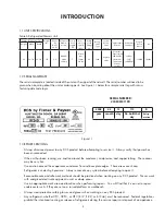
Страница 6: ...renches etc 12 Rivet gun and assorted rivets 13 Drill motor and assorted metal drills 14 Vacuum pump 15 1 5 Installation Unit can be installed freestanding or built in The front of the unit must be unobstructed for proper air circulation and operation at all times Unit must be on a LEVEL surface capable of supporting the loaded weight of the unit 1 6 Electrical Requirements WARNING ELECTRICAL SHOC...

Страница 7: ...below 40 degrees and above 100 degrees Fahrenheit Installation should be such that the unit can be moved for servicing if necessary 2 3 Cabinet Clearance Ventilation is required from the bottom front section of the unit Keep this area open and clear of any obstructions The adjacent cabinets and counter top can be built around the unit as long as no top trim or counter top is installed lower than t...

Страница 8: ... the refrigerated drawer Clean the inside of the appliance with warm water and a little liquid detergent to remove manufacturing and transporta tion dust Allow the refrigerated drawer to run empty for 2 3 hours to allow each compartment to cool to the appropriate temper ature The appliance may have an odor on its initial operation but this will go away when the refrigerated drawers have cooled suf...

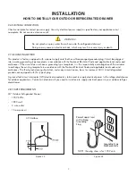
Страница 9: ...es not have a grounding type receptacle it is the responsibility and obligation of the customer to exchange the existing receptacle in accordance with the National Electrical Code and applicable local codes and ordinances The third ground prong should not under any circumstances be cut or removed All UL listed refrigerated products are equipped with this type of plug A ground fault circuit interru...

Страница 10: ...mark the screw hole locations Attach side trim to the inner side of the cabinet so that the trim faces outward away from the appliance s door and fasten with appropriate screws suitable for the type of cabinet material Fig 2 6 2 12 Installing Drawers Place the unit in front of the counter opening Make sure that the floor is protected when sliding the drawer unit into place Determine the minimum he...

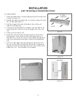
Страница 11: ...r point where the drawer will be draw a center line B Fig 2 7 perpendicular to line A to the rear of the unit Make a mark on line B 24 1 2 inches from line A 3 Then make another perpendicular line C at this mark Make a mark on line C 11 1 2 inches from line B either right or left 4 At this mark drill 1 8 diameter pilot hole in the floor 5 Fasten the bracket to the floor thru the slotted hole see F...

Страница 12: ... wall 5 Pull the unit away from the wall 6 Remove the screws that connect the upper and lower sections of the Anti Tip Bracket Mount the lower section of the bracket that is not attached to the unit to the wall where you had marked and drilled pilot holes in the wall wall stud for mounting Attach the lower bracket to wall 7 Push the unit back against the wall and align the upper section with the l...

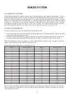
Страница 13: ...s will flush out any air or moisture that may 6 have entered the system before being absorbed into the ester oil 3 2 Low Side leaks Low side leaks consist of a break in the system at the evaporator low side suction return line or accumulator If a leak is found in any of these areas moisture has probably entered the system The compressor and drier will have to be replaced and the system will need t...

Страница 14: ...e thermocouple must be secured to the 1 evaporator when taking the measurement If it has been determined that there is proper contact between the thermistor and evaporator plate the thermistor 2 resistance value can be corresponded to the temperature see Table C in Section 5 2 Thermistors for values NOTE The temperature and pressure reading must be taken while the unit is on and running Use gage p...

Страница 15: ...ocess tube remove it and then seal the tube by brazing before charging Charge the unit to specified amount see Section 1 1 Unit Specifications for charge specifications per model After re charging the system check pressures and refer to Table B for corresponding temperatures and pressures If pressures are incorrect check the sealed system recover the charge repair evacuate and then re charge It is...

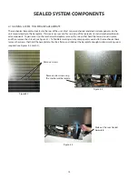
Страница 16: ...access to the mechanical baseplate remove the screws that hold the lower shroud in place and then remove the shroud see Figure 4 1 To facilitate working on any component mounted to the mechanical base remove the screws that hold the baseplate to the chair frame and slide out the baseplate enough to allow working room required see Figures 4 2 and 4 3 Figure 4 1 Remove screws Figure 4 2 Remove screw...

Страница 17: ...e compressor is faulty and will need to be replaced Removing the Compressor Disconnect power to the unit 1 Remove the back panel and lower shroud see Figure 4 1 2 Remove the screws that hold the baseplate to the chair frame of the unit and slide out the mechanical baseplate see Figures 3 4 2 and 4 3 Install sealed system access valve s and recover refrigerant After recovering be sure to cap off th...

Страница 18: ...d braze process tube Be sure to cap off end to prevent 3 any contamination Remove the plug for the suction line on the compressor Install and braze the suction line from the evaporator BE SURE TO 4 ALSO REINSTALL THE SUCTION LINE AND TUBING HARNESS INSULATION TUBES Reinstall the PTC starter and overload and wire according to the wiring diagram see page 28 Wiring 5 Reinstall the compressor cap 6 Re...

Страница 19: ...the baseplate to the chair frame of the unit and slide out the mechanical baseplate see Figures 3 4 2 and 4 3 Install sealed system access valve s and recover refrigerant After recovering be sure to cap off the access valve s to prevent 4 contamination of the system Remove the condenser fan by removing the four screws on the fan mounting bracket at the baseplate The fan wire leads can 5 be left co...

Страница 20: ...for the evaporator to frost up during its run cycle This frost will dissipate once the unit reaches its cut out tempera ture and the compressor and fan stop This condensate water will flow to the rear of the machine in a condensate pan where it will be evaporated from compressor and fan heat It is very important that the evaporator frosts in a uniform pattern across the plate see Section 3 6 Evapo...

Страница 21: ...nt draw is 0 19 amp or more check for resistance in air movement or objects touching the fan blade If this is not found replace the condenser fan Removing the Condenser Fan Disconnect power to the unit 1 Remove access panel and rear panel 2 Remove the grill by removing the screws and disconnecting the wires to the rocker switch Be sure to mark where these wires 3 go for reassembly Take out the scr...

Страница 22: ...l be displayed sequentially An audible alarm will also sound six times every minute if either one or both thermistors fails The thermistor can be checked by use of a multimeter with the ability to read resistance To check the thermistor Disconnect and remove thermistor from unit 1 Use a reference temperature point that is know such as an ice bath and measure the resistance across the wire leads 2 ...

Страница 23: ...aporator thermistor connector at the electronic controller 3 Remove evaporator thermistor by removing the screw securing it 4 Feed the thermistor wire out through the opening in the back of the unit 5 Installing the Evaporator Thermistor Reverse the removal procedure for installation see above System COMPONENTS ...

Страница 24: ...he temperature control is adjustable from the low 30s to the high 40s in the refrigerated drawers The setpoint out of the factory is approximately 38 degrees F The range or refrigerated drawers allows flexibility of temperature preferences and provides the ideal food storing temperatures The temperature can be lowered or raised by first pressing the SET button on the display panel A SET icon will ...

Страница 25: ...power failure or if the door is left ajar Door Ajar If the door is left open for more than five 5 minutes an audible alarm will sound three 3 times every 30 seconds and the LED light will flash green This will stop as soon as the door is closed High and Low Temperature If the unit reaches a temperature either above or below the set point temperature for more than one 1 hour an audible alarm will s...

Страница 26: ...tion Reference Error Code Error Code Reference Potential Causes of Failure E1 Compressor fault high low amps 1 Compressor wires disconnected 2 Faulty compressor 3 Faulty control 4 Faulty compressor overload 5 Faulty compressor PTC starter E2 Condenser fan motor fault high low amps 1 Condenser fan motor wires disconnected 2 Faulty condenser fan motor 3 Faulty control E3 Evaporator thermistor sensor...

Страница 27: ...rough 6 allow you to turn loads ON with the WARMER button and OFF with the COLDER button Tests 7 through 9 verify state change of the door switches and or magnetic reed sensor The component tests available are described in Table F Available Component Tests Table F Available Component Tests Test Component Description Available Status Indicators OK Off Open On Shorted 0 Temp Sensor A Evaporator 0 00...

Страница 28: ...oint of the front and rear edge of the lens Unhook lens from wire connector and remove it from the divider Disgard the lens 4 Attach wire connector to new lens and snap lens back into place 5 Reattach divider section to the unit 6 7 2 Drawers for Refrigerated Drawers Each drawer unit is equipped with two drawers a top and a bottom If necessary the drawer fronts can be adjusted Adjusting the Drawer...

Страница 29: ...t grill 3 Turning off the Heater Strip Reverse the turn on procedure above to turn off the heater strip 7 6 CIRCULATION FAN ASSEMBLY The circulation fan moves air within the entire cabinet across the evaporator to maintain the proper set temperature zones The fan is located behind the evaporator plate on the back wall To remove the circulation fan remove both drawers Remove the screws holding the ...

Страница 30: ...28 23 WIRING DIAGRAM ...

Страница 31: ...located on the serial nameplate see Section 1 2 Serial Nameplate 1 Color of the model 2 Metal or plastic grill 3 Type of door 4 To order parts call or write Fisher Paykel Appliances Inc Attention DCS Customer Care 5900 Skylab Road Huntington Beach CA 92647 phone 888 936 7872 www dcsappliances com Ordering Parts ...

Страница 32: ...ithin seven seconds Press and hold the SET button while pressing the F C button seven times within seven seconds NOTE Holiday Mode will automatically disable after 36 hours Audible alarm sounding three times every 30 seconds and LED light flashing green 1 Door Ajar alarm Close the door Audible alarm sounding six times every minute and LED light flashing red 1 High and Low Temperature alarm Press t...

Страница 33: ...is not engaging 1 Did not press the WARMER and COOLER buttons the correct amount of times in the allotted time period To enable press and hold the WARMER button while pressing the COOLER but ton four times within five seconds Service Mode disabled automatically 1 After five minutes of no key pad entry Service Mode will automatically disable To restart press and hold the WARMER button while pressin...

Страница 34: ...chase price of the Product not including installation or other charges This warranty extends to the original purchaser and any succeeding owner of the Product for products purchased for ordinary single family home use All service under this Limited Warranty shall be provided by Fisher Paykel Appliances Inc or its Authorized DCS Service Agent during normal business hours Limited Warranty How Long D...

Страница 35: ... damages so the above limitation or exclusion may not apply to you How to get service Please read this Use and Care Guide If you then have any questions about operating the Product need the name of your local DCS Authorized Service Agent or believe the Product is defective and wish service under this Limited Warranty please contact your dealer or call us at TOLL FREE 1 888 936 7872 or contact us t...

Страница 36: ...34 NOTES ...

Страница 37: ...35 NOTES ...

Страница 38: ...36 NOTES ...

Страница 39: ......

Страница 40: ...ad Huntington Beach CA 92647 Customer Care 888 936 7872 Fax 714 372 7003 www dcsappliances com P N 243199 Rev A Litho in USA 10 2008 As product improvement is an ongoing process we reserve the right to change specifications or design without notice ...

Отзывы: