26
7.1 lightS
For Refrigerated Drawers:
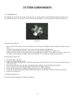
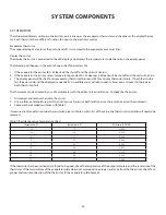
The refrigerated drawers are equipped with two lights: one on the inside top of the drawer and one in the divider.
Replacing the Top Light:
Loosen the screws to the control housing. You do not need to remove them.
1.
Pull the control housing forward out of the screw slots.
2.
Look inside the control housing and remove the wire connector to the light.
3.
Press down and out on the LED bulb and lens. You will need to press the release tab on the lens.
4.
Remove old bulb and set aside.
5.
Insert new bulb and reverse steps 1-4 to complete.
6.
Replacing the Divider Light:
Remove screws to the divider section and pull the divider out from the unit.
1.
Flip the divider over for easier access to the lens assembly. Be careful not to disturb other wiring inside the unit.
2.
Press in on the lens release tabs while simultaneously prying the lens upward using a flat-blade screwdriver. The release tabs
3.
are located at the midpoint of the front and rear edge of the lens.
Unhook lens from wire connector and remove it from the divider. Disgard the lens.
4.
Attach wire connector to new lens and snap lens back into place.
5.
Reattach divider section to the unit.
6.
7.2 drawerS (for refrigerated drawerS)
Each drawer unit is equipped with two drawers: a top and a bottom. If necessary, the drawer fronts can be adjusted.
Adjusting the Drawer Fronts:
Loosen the screws along the inside perimeter of the drawer.
1.
Position drawer as desired.
2.
Retighten the screws along the inside perimeter of the drawer.
3.
7.3 glideS
Each drawer has its own glide that it slides upon when opened or closed. The glides cannot be adjusted and should not be
greased or lubed. Each glide should be kept clean. If one or both glides were to become contaminated or dirty, they must be
cleaned. Use soap and water to clean them.
7.4 divider/center Section
The divider is the center section of the drawer unit. It separates the top drawer from the bottom drawer. If the divider develops
condensation on it, the heater option can be turned on to prevent this from occurring (see Section 7.5, Heater Strip).
INTErIOr COMPONENTS
Содержание RF24-D
Страница 1: ...1 DCS REFRIGERATED DRAWERS Service manual Model RF24D ...
Страница 2: ......
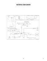
Страница 30: ...28 23 WIRING DIAGRAM ...
Страница 36: ...34 NOTES ...
Страница 37: ...35 NOTES ...
Страница 38: ...36 NOTES ...
Страница 39: ......

