31
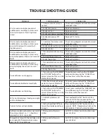
PROBLEM
POSSIBLE CAUSE
CORRECTION
E1 error code on display panel and
audible alarm sounding six times every
minute (Compressor fault - high/low
amps).
1. Compressor wires discon-
nected.
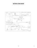
Check wiring diagram on back of unit and
reconnect wires.
2. Faulty compressor.
Replace compressor.
3. Faulty control.
Replace control.
4. Faulty compressor overload. Replace overload.
5. Faulty compressor PTC
starter.
Replace PTC starter.
E2 error code on display panel and
audible alarm sounding six times every
minute (Condenser fan motor fault -
high/low amps).
1. Condenser fan motor wires
disconnected.
Check wiring diagram on back of unit and
reconnect wires.
2. Faulty condenser fan motor. Replace condenser fan motor.
3. Faulty control.
Replace control.
E3 error code on display panel and
audible alarm sounding six times every
minute (Evaporator thermistor “sensor B”
fault).
1. Disconnected wire causing
open.
Check wiring diagram on back of unit and
reconnect wires.
2. Shorted thermistor wires.
Replace thermistor.
3. Faulty thermistor.
Replace thermistor.
E4 error code on display panel and
audible alarm sounding six times every
minute (Display thermistor “sensor A”
fault).
1. Disconnected wire causing
open.
Check wiring diagram on back of unit and
reconnect wires.
2. Shorted thermistor wires.
Replace thermistor.
3. Faulty thermistor.
Replace thermistor.
Service Mode is not engaging.
1. Did not press the “WARMER”
and “COOLER” buttons the
correct amount of times in the
allotted time period.
To enable, press and hold the “WARMER”
button while pressing the “COOLER” but-
ton four times within five seconds.
Service Mode disabled automatically.
1. After five minutes of no key-
pad entry, Service Mode will
automatically disable.
To restart, press and hold the “WARMER”
button while pressing the “COOLER” but-
ton four times within five seconds.
Service Mode is not disabling.
1. Did not press the “WARMER”
and “COOLER” buttons the
correct amount of times in the
allotted time period.
To exit, press and hold the “WARMER” but-
ton while pressing the “COOLER” button
four times within five seconds.
LED is not displaying a steady green light
on the display panel.
1. Control System was dis-
abled.
Press and hold the “SET” button for five
seconds. NOTE: Steady green light on the
LED indicates Control System engaged.
Control System will not disable.
1. Did not hold the “SET” but-
ton on the display panel long
enough.
Press and hold the “SET” button for five
seconds. NOTE: Steady amber light on the
LED indicates Control System disabled.
Software model number does not match
the unit purchased, i.e. - 11 should cor-
respond to a 24 in. wine cellar.
1. Wrong unit software in-
stalled.
Call DCS Customer Service to obtain new
user interface.
Temperature range for the unit does not
correspond to the temperature range
given by DCS (out-of-range).
1. Wrong unit software in-
stalled.
Call DCS Customer Service to obtain new
user interface.
TrOuBLESHOOTING GuIdE
Содержание RF24-D
Страница 1: ...1 DCS REFRIGERATED DRAWERS Service manual Model RF24D ...
Страница 2: ......
Страница 30: ...28 23 WIRING DIAGRAM ...
Страница 36: ...34 NOTES ...
Страница 37: ...35 NOTES ...
Страница 38: ...36 NOTES ...
Страница 39: ......


